QUANTUM
™
LX EVAPORATOR CONTROL PANEL
COMMUNICATIONS SETUP
090.610-CS (MAY 2016)
Page 112
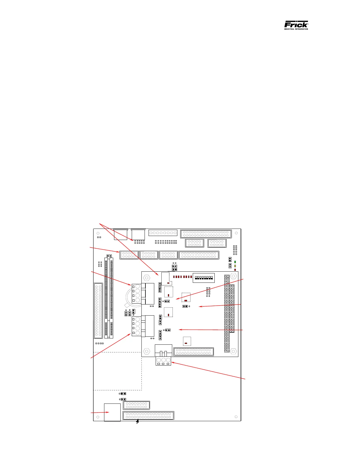
Q4 CONTROLLER
MAIN BOARD HISTORY AND IDENTIFICATION
The processor board shown on this page is known as
the Q4 board, and it is based on the Pentium micro-
processor platform. The operating software that this
board runs is known as Quantum™ LX software. This
software displays graphic information and data on the
LCD screen in a format that is similar to the way a
Windows® desktop computer screen displays a Web
browser (the Internet).
The Q4 board can be identied by the presence of
a daughter board mounted to the main board. This
daughter board is the communications portion of the
Q4, and it can be identied by the presence of an 8 po-
sition DIP switch. There are also a number of jumpers
(or links) present on this smaller board, as well as three
green connectors (RS-232, RS-422 and RS-485 ports).
The jumpers are used to set up the communications
parameters that are listed on the next page.
The main board (larger of the two) has a number of
jumpers (or links) also. The links on this board MAY
need to be modied by qualied personnel to congure
the Quantum™ 4 for specic applications.
The Q4 utilizes Flash Card technology, as did the Q3.
There is a Flash Card socket located on the under side
of this main board. The Q4 board has the LX Operating
System pre-loaded at the factory, so this Flash Card
feature will primarily be utilized for future program up-
dates.
When calling Frick® Company for service or help, it
will greatly assist us if the type of board is known, ei-
ther Q1, 2, 3 or 4. Additionally, Frick® will request the
Sales Order number, and the Operating System version
number (this can be found on the About… screen). The
more information available at the time of the call, the
better able we will be to assist you.
The information that follows will primarily describe the
jumper conguration for communications settings, as
well as wiring diagrams for the different types of com-
munications that are possible with the Q4.
Keypad
9
Flash Card Socket
(Located under board)
12
5
COM2
6
5
1
2
422
4
3
6
5
422
8
7
9
COM2
RS-232
Connector
USB Connector
(Depending on board version, USB could be
located in either of these two places).
Com-1
(TB1)
RS-422/485
Connector
Com-2
(TB2)
RS-422/485
Connector
(TB3)
RS-232
Connector
between using
RS-422/485 on
Com-2 (TB2)
OR
RS-232 on
Com-2 (TB3)
between
RS-422 and
RS-485 for
Com-1 (TB1).
LK17 selects
between
RS-422 and
RS-485 for
Com-2 (TB2).