QUANTUM
™
LX EVAPORATOR CONTROL PANEL
COMMUNICATIONS SETUP
090.610-CS (MAY 2016)
Page 120
COMMUNICATIONS LOOPBACK TEST
DESCRIPTION
NOTE: Communications Loopback testing is not
yet available for the Q5.
The purpose of this section is to verify the proper
operation of the following communications ports:
Comms 1 (TB1) and 2 (TB2) - RS-422
Comms 1 (TB1) and 2 (TB2) - RS-485
Comms 2 (TB2) and 3 (PL6) – RS-232
By utilizing a loopback test harness (as shown on
the following pages), the technician has the abil-
ity to locally test the Quantum™ communications
hardware and jumper conguration.
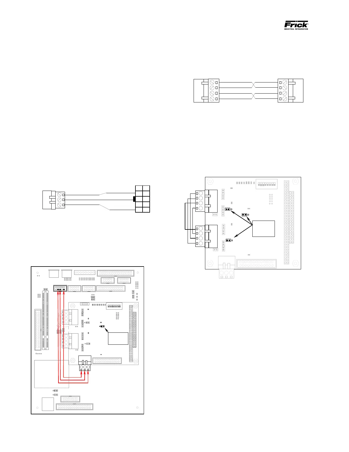
HARDWARE SETUP FOR TESTING RS-232
To create the communications loopback harness
for RS-232 testing, use the following example(s):
Q4 RS-232 Test Harness
Set the communications jumpers as follows:
• Set LK11 to position A
• Plug the RS-232 test harness (as shown
above) into the Com ports at TB3 and
PL6.
Flash Card Socket
(Located under
board)
1
RS-422
RS-
422
LK11 is set to A
Com-2 (TB3) & Com-3 (PL6) RS-232 Connector &
Jumper Location
HARDWARE SETUP FOR TESTING RS-422
To create the communications loopback harness
for RS-422 testing, use the following example(s):
Q4 RS-422 Test Harness
Set the communications jumpers as follows:
1. Set LK11 to position B
2. Set LK16 to position A
3. Set LK17 to position A
4. Plug the RS-422 test harness (as shown
above) into the com ports at TB1 and TB2
as shown here:
the jumpers in
these locations
Q4 RS-422 Test Conguration