QUANTUM
™
LX EVAPORATOR CONTROL PANEL
COMMUNICATIONS SETUP
090.610-CS (MAY 2016)
Page 38
ASCII
In ASCII mode, messages start with a co-
lon ( : ) character (3A hex), and end with
a carriage return-line feed (CRLF) pair
(0D and 0A hex).
The allowable characters transmitted for
all other elds are hexadecimal 0 - 9, A
- F.
All Quantum™ panels connected to the
network monitor the network bus con-
tinuously for the colon character. When
one is received, each Quantum™ de-
codes the next eld (the address eld) to
nd out if it is the addressed device.
A MODBUS® message is placed by the
transmitting device into a frame that has
a known beginning and ending point.
This allows receiving devices to begin at
the start of the message, read the ad-
dress portion and determine which de-
vice is addressed, and to know when the
message is completed. Partial messages
can be detected and errors can be set as
a result.
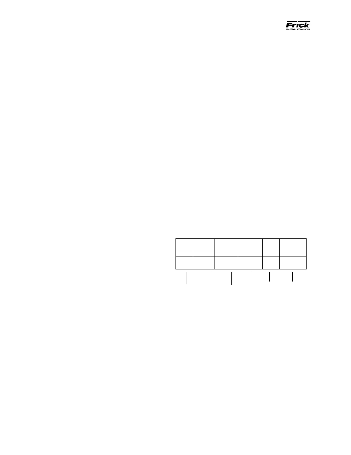
A typical message frame as sent by the
Master is shown below:
START ADDRESS FUNCTION DATA
LRC
CHECK
END
: 01 03 00870001 74 CRLF
1
CHAR
2
CHAR
2
CHAR
8
CHAR
2
CHAR
2
CHAR
RTU
In RTU mode, messages start with a si-
lent interval of at least 3.5 character
times. This is most easily implemented as
a multiple of character times at the baud
rate that is being used on the network
(shown as T1–T2–T3–T4 in the gure
below). The rst eld then transmitted is
the device address.
The allowable characters transmitted for
all elds are hexadecimal 0–9, A–F. Net-
worked devices monitor the network bus
continuously, including during the ‘silent’
intervals. When the rst eld (the ad-
00 = H. O. Address
87 = L. O. Address
00 = H. O. # of data registers
01 = L. O. # of data registers
End of
message
CRC Error
Correction
Code
Start of
message
Quantum™
ID
Function
RTU
In RTU mode, messages include an error–
checking eld that is based on a Cyclical
Redundancy Check (CRC) method. The CRC
eld checks the contents of the entire mes-
sage. It is applied regardless of any parity
check method used for the individual char-
acters of the message.
The CRC eld is two bytes, containing a 16–
bit binary value. The CRC value is calculated
by the transmitting device, which appends
the CRC to the message. The receiving de-
vice recalculates a CRC during receipt of
the message, and compares the calculated
value to the actual value it received in the
CRC eld. If the two values are not equal an
error results.
The CRC is started by rst preloading a 16–
bit register to all 1’s. Then a process be-
gins of applying successive 8–bit bytes of
the message to the current contents of the
register. Only the eight bits of data in each
character are used for generating the CRC.
Start and stop bits, and the parity bit, do not
apply to the CRC.
During generation of the CRC, each 8–bit
character is exclusive ORed with the regis-
ter contents. Then the result is shifted in the
direction of the least signicant bit (LSB),
with a zero lled into the most signicant
bit (MSB) position. The LSB is extracted and
examined. If the LSB was a 1, the register
is then exclusive ORed with a preset, xed
value. If the LSB was a 0, no exclusive OR
takes place.
This process is repeated until eight shifts
have been performed. After the last (eighth)
shift, the next 8–bit byte is exclusive ORed
with the register’s current value, and the
process repeats for eight more shifts as de-
scribed above. The nal contents of the reg-
ister, after all the bytes of the message have
been applied, is the CRC value.
When the CRC is appended to the message,
the low-order byte is appended rst, fol-
lowed by the high-order byte.
Framing
A message frame is used to mark the beginning
and ending point of a message allowing the re-
ceiving device to determine which device is be-
ing addressed and to know when the message is
completed. It also allows partial messages to be
detected and errors agged as a result.