QUANTUM
™
LX EVAPORATOR CONTROL PANEL
COMMUNICATIONS SETUP
090.610-CS (MAY 2016)
Page 114
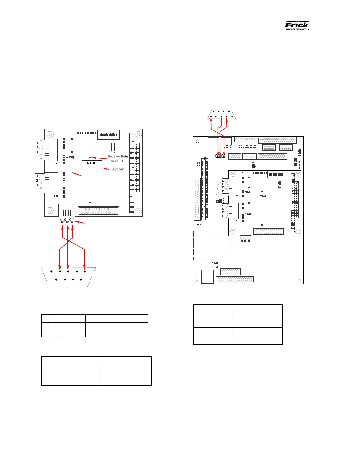
SERIAL COMMUNICATIONS PORT WIRING
RS-232 WIRING AND JUMPERS
COM-2 (TB3)
The following pictorial shows the communi-
cations board, as well as the jumpers, LED’s
and signal pinouts to allow the end user to
communicate to Com-2 (TB3) using RS-232
protocol. Refer to the tables in this section
for the specics on the jumper settings and
wiring convention for RS-232.
RS-232 TB3
3-Pin Connector
PC or PLC
9-Pin
COM
80H
0
1
RS-
422
RS-
422
RS-232 Com-2 (TB3) Communications Wiring
RS-232 Com-2, TB3 Communications Board
Jumpers
LINK POSITION FUNCTION
LK11
A *
B
RS-232 for COM2 (TB3)
RS-422 for COM2 (TB2)
* Standard Setting
RS-232 Com-2, TB3 Communications Signals
TB3 Connector Pin # Signal
1
2
3
Transmit Data (TX)
Received Data (RX)
Ground (COM)
COM-3 (PL6)
The following pictorial shows the communications
board, as well as the jumpers, LED’s and signal pin-
outs to allow the end user to communicate to Com-3
(PL6) using RS-232 protocol. Refer to the table entitled
Com-3, PL6 Communications Signals for the specics
on the jumper settings and wiring convention for RS-
232. NOTE: There are NO jumper settings associated
with this connector (Com-3).
Flash Card Socket
(Located under
board)
RS-
RS-
422
1
9-Pin
RS-232 Com-3 (PL6) Wiring To 9-Pin D-Connector
RS-232 Com-3, PL6 Communications Signals
PL6 Connector
Pin #
Signal
3 Received Data (RX)
5 Transmit Data (TX)
9 Ground (COM)