QUANTUM
™
LX EVAPORATOR CONTROL PANEL
COMMUNICATIONS SETUP
090.610-CS (MAY 2016)
Page 121
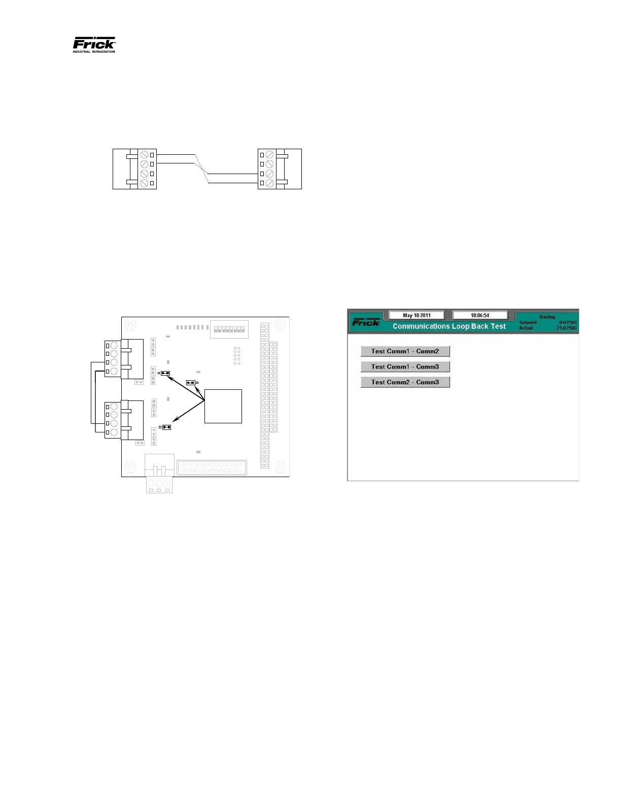
HARDWARE SETUP FOR TESTING RS-485
To create the communications loopback harness
for RS-422 testing, use the following example:
RS-485 Test Harness
Set the communications jumpers as follows:
1. Set LK11 to position B
2. Set LK16 to position B
3. Set LK17 to position B
4. Plug the RS-485 test harness (as shown
above) into the com ports at TB1 and TB2
as shown here:
the jumpers in
these locations
RS-485 Test Conguration
SOFTWARE SETUP FOR THE COMMUNICATIONS LOOP-
BACK TEST
On the Communications screen (shown below), ensure
that the settings are as follows:
• Panel ID: 0 - 255 (does not matter)
• Comm Baud Rate: Does not matter, but all
Comms to be tested must be set the same.
• Data Bits: Does not matter, but all Comms to
be tested must be set the same.
• Stop Bits: Does not matter, but all Comms to
be tested must be set the same.
• Parity: Does not matter, but all Comms to be
tested must be set the same.
• Protocol: Set all Comms to be tested to Frick.