QUANTUM
™
LX EVAPORATOR CONTROL PANEL
COMMUNICATIONS SETUP
090.610-CS (MAY 2016)
Page 116
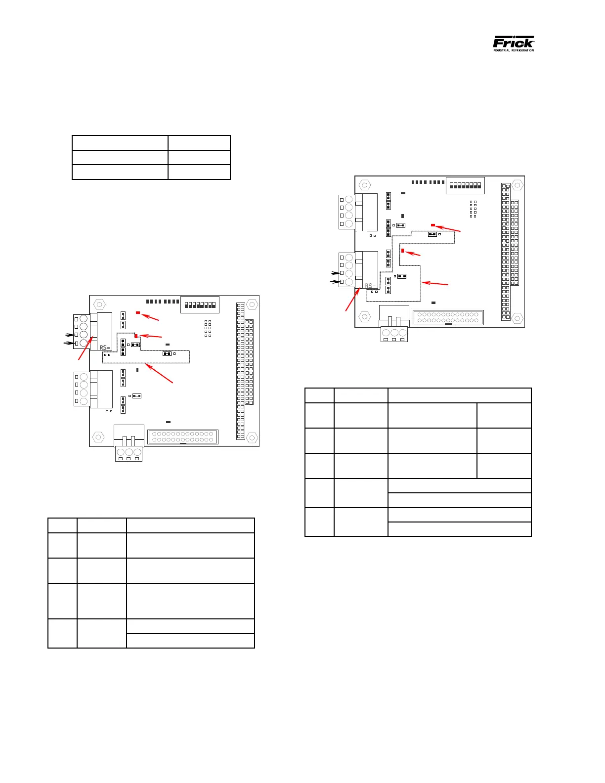
COM-2 (TB2)
The following pictorial shows the communi-
cations board, as well as the jumpers, LED’s
and signal pinouts to allow the end user to
communicate to Com-2 (TB2) using RS-485
protocol. Refer to the tables in this section
for the specics on the jumper settings and
wiring convention for RS-485:
485 Connector
0
1
PL3
RS-485 Com-2 (TB2) Connector, Jumpers and LED Location
RS-485 (TB2) Communications Board Jumpers
LINK POSITION FUNCTION
LK 1
In
Out*
Terminate COM2
No termination
RS-485
LK 3
In
Out*
Pull down COM2
No pull down
RS-485
(-TX /-RX)
LK 4
In
Out*
Pull up COM2
No pull up
RS-485
(+TX /+RX)
LK 11
A
B*
Select RS-232 for COM2 (TB3)
Select RS-485 for COM2 (TB2)
LK 17
A
B *
COM2 RS-422 (TB2)
COM2 RS-485 (TB2)
* Standard Setting
RS-485 WIRING AND JUMPERS
The following table describes the RS-485 connector
pinouts and their associated communications signals:
RS-422 (TB1) Communications Signal Wiring
TB1 Connector Pin # Signal
2 +TX / +RX
1 -TX / -RX
COM-1 (TB1)
The following pictorial shows the communi-
cations board, as well as the jumpers, LED’s
and signal pinouts to allow the end user to
communicate to Com-1 (TB1) using RS-485
protocol. Refer to the tables on this page for
the specics on the jumper settings and wir-
ing convention for RS-485:
0
1
485 Connector
RS-485 Com-1 (TB1) Connector, Jumpers and LED Location
RS-485 (TB1) Communications Board Jumpers
LINK POSITION FUNCTION
LK2
In
Out*
Terminate COM1
No termination
RS-485
LK7
In
Out*
Pull down COM1
No pull down
RS-485
(-TX / -RX)
LK8
In
Out*
Pull up COM1
No pull up
RS-485
(+TX /
+RX)
LK16
A
B *
COM1 RS-422 (TB1)
COM1 RS-485 (TB1)
* Standard Setting