About Your SONAbeam Terminal
6
wireless at the speed of light …………….
NAbeam E-Series Installation Manual
class device that offers protocol independent optical interfaces that are unmatched in the
industry.
With proper planning and pre-installation preparation, a complete network link can be
installed and commissioned in a matter of hours and provide lasting reliable operation to
meet your networking requirements.
The planning stage entails a prescribed site survey of your proposed installation areas to
ascertain the suitability of your sites and to assist in optimally locating the SONAbeam
terminals once the general link location is validated. The survey also affords you an
opportunity to map out all of the necessary mechanical, electrical and network
infrastructure to support the terminals.
The installation stage is designed to be simple and straightforward requiring ordinary
electrical equipment installation skills and common tools.
While the configuration setup and alignment stage does require some special equipment
and fSONA software, the step-by-step procedures provided by this manual will help you
to successfully and quickly complete this task.
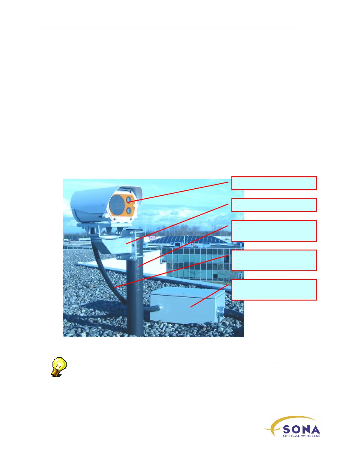
Figure 2 – SONAbeam E-Series System Installation Components (roof top location)
NOTE…
The installer-provided Customer Interface Box must have the appropriate NEMA
rating for your application. If installed outdoors, a NEMA 3 rating is
recommended…
SONAbeam Optical Head
Mounting Mast
(Provided by the Installer)
Customer Interface Box
(Provided by the Installer)
Customer Cabling Kit
(Provided by the Installer)
Optional Post Mount