Aligning Your SONAbeam Terminals
wireless at the speed of light …………….
61
-Series Installation Manual
Stage 1 – Visual Alignment
The initial visual alignment stage is necessary to establish terminal alignment within the
terminal’s field of view to be able to use a measured alignment procedure described later
in this guide.
WARNING!
NEVER use optical instruments to view an operating SONAbeam terminal at a
range closer than 50 meters (170 feet)!
NOTE…
The Alignment Telescope provided by fSONA is altered with a special spectral
filter that lets you safely view a SONAbeam terminal.
The visual alignment stage is meant to get your alignment close enough to be able to use
the alignment tuning controls for the next stage. To achieve visual alignment, proceed as
follows:
1.
Power both SONAbeam terminals OFF!
2.
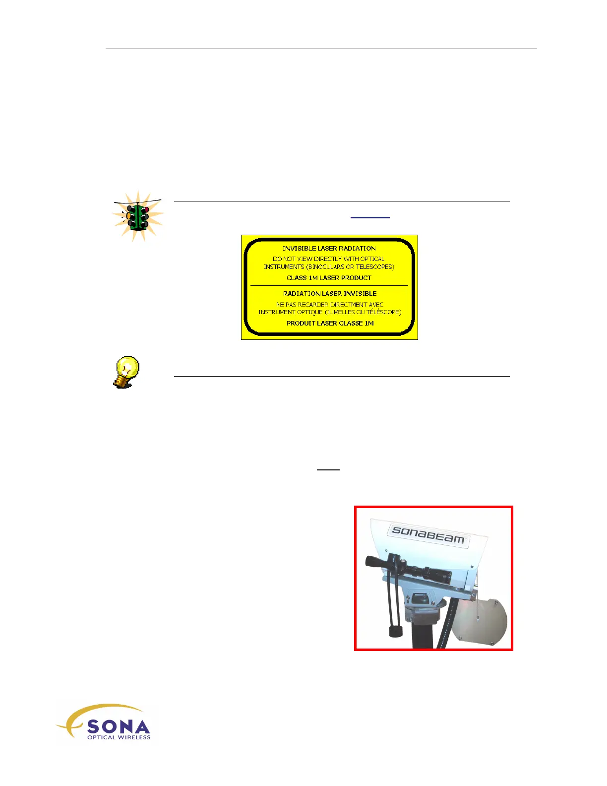
Mount a SONAbeam Alignment Telescope (part of the optional Basic
Alignment Kit) onto each optical head, as shown in Figure 27.
Figure 27 – Attached Alignment Telescope