Aligning Your SONAbeam Terminals
68
wireless at the speed of light …………….
NAbeam E-Series Installation Manual
Received Signal Strength Guide
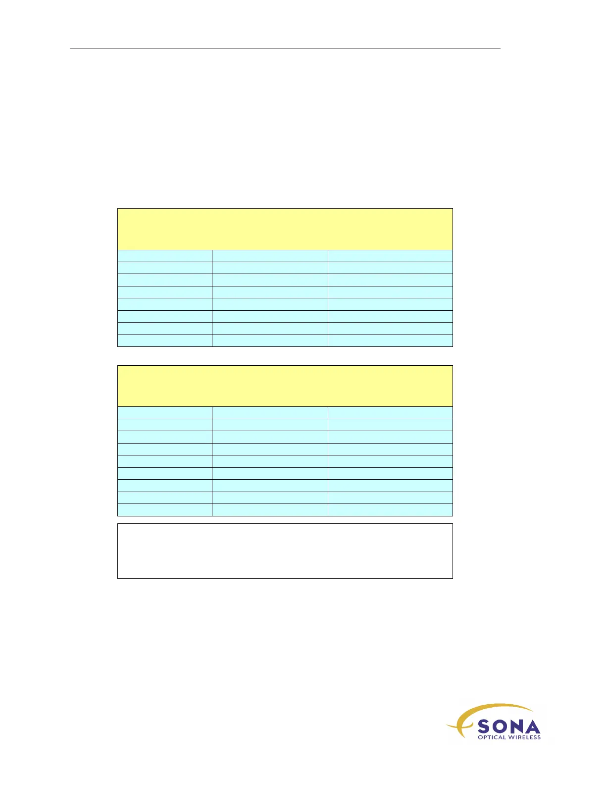
The following tables are offered to assist you in gauging when your terminal alignment is
optimal. This information is to be used ONLY as a guide, as daily conditions at your
installation site can affect the received power levels for your particular link. Still, the
information from this table can prove helpful when aligning your SONAbeam link.
155-E:
‘Typical’ Clear-Air Receive Signal Strength*
SONAbeam 155-E Series Terminals @ Laser Pwr Index = 14
Range (meters) STC display (µwatts) Voltmeter
100 900 (Power Index = 6) 4.0 V
150 650 (Power Index = 8) 3.0 V
250 900 4.0 V
500 220 1.0 V
750 90 410 mV
1000 50 230 mV
1500 20 100 mV
2000 10 60 mV
1250-E:
‘Typical’ Clear-Air Receive Signal Strength*
SONAbeam 1250-E Series Terminals @ Laser Pwr Index = 14
Range (meters) STC display (µwatts) Voltmeter
200 330 (Power Index = 8) 5.7 V (Power Index = 8)
300 360 (Power Index = 12) 6.1 V (Power Index = 12)
350 420 7.0 V
400 320 5.6 V
500 200 4.0 V
750 90
1000 50 1.8 V
1200 35 1.3 V
1500 20 0.8 V
*
Clear-weather conditions, with optimal alignment
*
No windows or partial beam obstructions
*
Lasers operated at full-power (unless otherwise specified)
*
Results can vary ±20% (±1 dB) due to smog, haze, and manufacturing variations