Initial Power Up and Terminal Configuration
54
wireless at the speed of light …………….
NAbeam E-Series Installation Manual
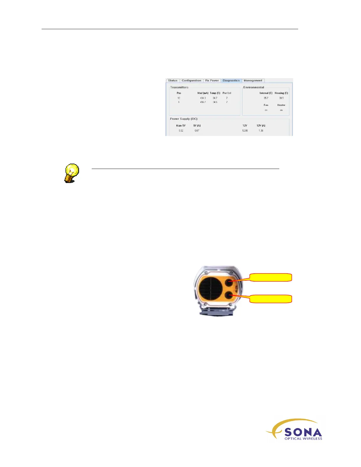
SONAbeam Diagnostics
After completing the initial
Configuration Wizard, view the STC’s
Diagnostics
screen, which reports your
terminal operating parameters, to finalize
the initial power-up verification process.
Figure 22 – SONAbeam Terminal Controller – Diagnostics Window
NOTE…
Perform the initial setup to both SONAbeam terminals when building an
FSO link…
SONAbeam Transmitter Orientations
The two optical transmitters on the
SONAbeam E-Series are referred to by their
relative clock-face positions, as shown in
Figure 23
Figure 23 – SONAbeam E-Series
Transmitter Orientations
12 o’clock