4
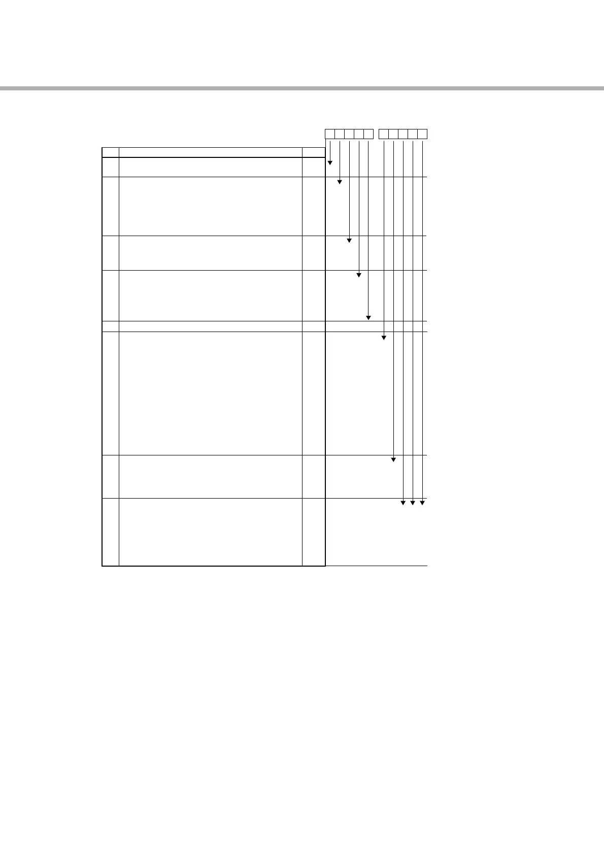
Specification
45678
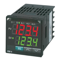
PXR
4
5
6
7
8
9
10
11
12
13
4
1
-
T
R
N
S
A
B
A
C
E
Y
A
C
E
R
1
0
1
2
3
4
5
6
7
F
G
H
M
D
P
N
V
C
B
0
M
N
S
T
V
W
0
0
0
0
0
0
0
0
0
0
0
0
0
0
<Front dimensions>
48 X 48mm
<Input signal>
Thermocouple °C
Thermocouple °F
Resistance bulb Pt100 3-wire type °C
Resistance bulb Pt100 3-wire type °F
1 to 5V DC
4 to 20mA DC
<Control output 1>
Relay contact output
Voltage pulse output (24V DC)
4 to 20mA DC output
<Control output 2>
None
Relay contact output
Voltage pulse output (24V DC)
4 to 20mA DC output
Re-transmission output (4 to 20mA DC)
<Revision code>
<Optional specifications 1>
None
Alarm (1 pc.)
Alarm for heater break
Alarm (1 pc.) + Alarm for heater break
Ramp-soak
Alarm (1 pc.) + Ramp-soak
Alarm for heater break + Ramp-soak
Alarm (1 pc.) + Alarm for heater break + Ramp-soak
Alarm (2 pcs.)
Alarm (2 pcs.) + Ramp-soak
Alarm (2 pcs.) + Alarm for heater break + Ramp-soak
Alarm (3 pcs.)
Remote SV
Remote SV + Alarm (2 pcs.)
<Instruction manual> <Power supply voltage>
None 100 to 240V AC
English 100 to 240V AC
None 24V DC
English 24V DC
<Optional specifications 2>
None
RS485 (Modbus) communication
RS485 (ASCII) communication
Digital input 1 point
Digital input 2 points
RS485 (Modbus) communication + Digital input 1 point
RS485 (ASCII) communication + Digital input 1 point
910111213
Digit
Note 1
Note 2
Note 2
Note 2
Note 2
Note 3
Note 3
Note 3
Note 3
Note 3
Note 3
Note 3
Note 4
Note
Note 1: Cannot be combined with heater break alarm.
( 2, 3, 6, 7, H cannot be specified on 9th digit.)
Note 2: Cannot be combined with alarm (1 pc.) + heater break alarm, alarm (2 pcs.), or alarm (3pcs.).
( 3, 7, F, G, H, M, P cannot be specified on 9th digit.)
Note 3: Cannot be combined with RS485 + 1-point digital input.
(V and W cannot be specified on 11th digit.)
Note 4: In the case of control output 2, either of heater break alarm or remote SV input can be selected.
(A, C, E and R on the 7th digit, and 2,3,6,7,H, D and P on the 9th digit cannot be specified.)
Input signal, measurement range, and set value at the time of deliver are as follows.
When thermocouple is specified: Thermocouple K, Measurement range; 0 to 400°C, Set value; 0°C
When resistance bulb is specified: Pt, Measurement range; 0 to 150°C, Set value; 0°C
When voltage/current is specified: Scaling; 0 to 100%, Set value; 0%
For the cases other than the above, specify input signal and measurement range.
Input signal of the thermocouple and the resistance bulb can be switched by key operation on the front panel.
The actuating method of the control output has been set to reverse for control output 1, and to direct for control
output 2 at the time of delivery. Note that reverse and direct actuation can be switched by key operation on the
front panel.
PXR4