Machine Components
65
Product Overview
2
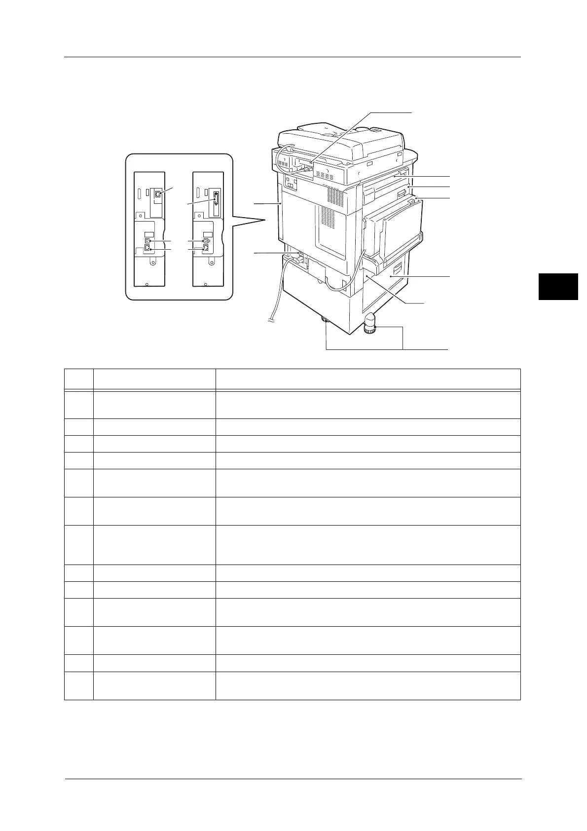
Left and rear view
This view varies depending
on optional components.
No. Component Function
1 USB 2.0 interface connector
(optional)
Connects to the cable of a Memory Card Reader or a USB memory device.
2 Cover E Open this cover to clear paper jams.
3 Cover A Open this cover to clear paper jams.
4 Cover D Open this cover to clear paper jams.
5 Cover C Open this cover to clear paper jams. When Tray 6 is installed, open this cover
after moving Tray 6 to the left.
6 Cover B Open this cover to clear paper jams. When Tray 6 is installed, open this cover
after moving Tray 6 to the left.
7 Adjusting foot Prevents the machine from toppling over. Move the machine to its
installation site and then rotate this adjuster in the clockwise direction until
it touches the floor.
8 RESET button Automatically switches the machine off when a current leakage is detected.
9 Rear right cover Open this cover when connecting an interface cable.
10 Secondary Ethernet
connector (optional)
Connects to a network cable. Can be used as Gigabit Ethernet interface
connector.
11 Parallel interface connector
(optional)
Connects to a Centronics-conformed interface cable, and connects the
machine to a computer.
12 USB 2.0 interface connector Connects a USB cable for printing.
13 10BASE-T/100BASE-TX
connector
Connected to a network cable. To use this as a Gigabit Ethernet interface
connector, install the Gigabit Ethernet Kit (optional).
 Loading...