RB-RBC-IOMM-2015-1
Fulton Ltd
Page 7
INSTALLATION - 2
2.5 FLUE OUTLET
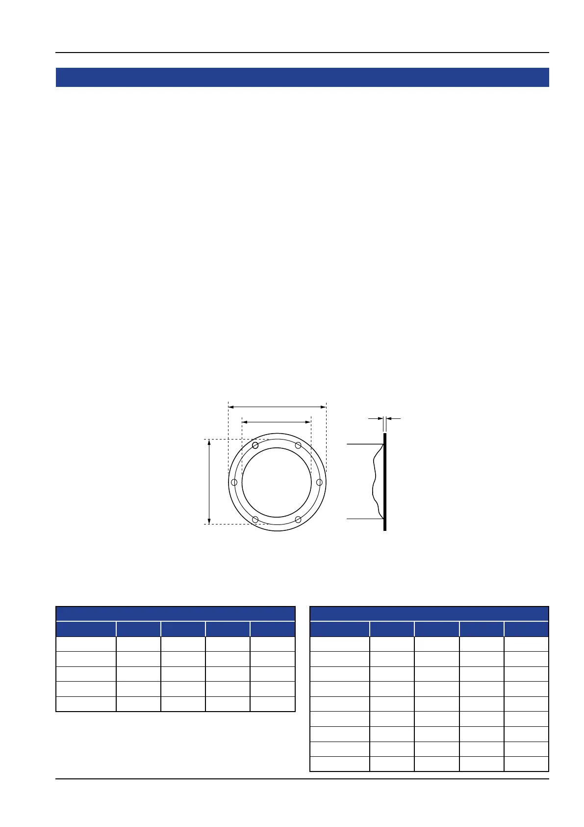
Figure. 3 - Boiler Flue Flange
Theheightandtypeofuewillbesubjecttolocalplanningregulationsandapprovals,andtothe
requirements of the Clean Air Act or similar local regulations.
Note: Before erecting a ue, Public Health Authority and Planning permission must be obtained.
Thefollowinginformationisintendedtoprovideassistancewheretheinstallationofasimpleue
is required.Wheremulti-boileruesarenecessary,ordifcultiescouldbeexperienced,specialist
advice must be obtained.
Boilersarettedwithaangedueoutlet.Theuemanufacturer/installermustbeconsultedatan
earlystagetoensureacorrectmatingcomponentforueconnection(seeFigure.3).
Theuediametermustbethesameorlargerthantheboilerueoutlet.Areductioninue
diameter will cause additional resistance which could have an adverse effect on combustion.
Note: Avoid tting 90° short radius elbows, 90° tees and long horizontal runs wherever possible.
Note: All horizontal ue runs should have a rising pitch of 15° minimum to prevent condensate build-up and
subsequent corrosion.
Note: Oil-red boiler installations are generally more critical because of the sulphur content in the fuel and the
higher dew-point temperature.
Note: Specialist advice should be obtained on ue material and insulation.
A
B
C
12 mm
RBC Flue Connection
Holes 15mm dia. equi-spaced
Material mild steel
RB Flange
Model A B C (PCD) Holes
1600 400 300 360 6
2600 450 350 410 6
3400 550 450 510 6
4800 600 500 560 8
5500 650 550 610 8
RBC Flange
Model A B C (PCD) Holes
600 350 250 310 6
750 400 300 360 6
1000 400 300 360 6
1250 450 350 410 6
1500 500 400 460 6
1850 550 450 510 6
2100 550 450 510 6
2500 600 500 560 8
3000 650 550 610 8