RB-RBC-IOMM-2015-1
Fulton Ltd
Page 13
INSTALLATION - 2
An individual wiring diagram for the boiler is located on the inside cover of the control box.
Whenreferringtotheelectricalspecicationoftheboiler,thereferencenumberlocatedonthe
rear inside wall of the control box and the wiring diagram number should be quoted.
The audible alarms provided are mounted on the front of the control panel, if not audible they
should be repositioned where they can be heard by a person competent to take the appropriate
action should the alarm be activated.
A 3-phase, neutral and earth isolated supply is required; this should be connected to the supply
terminals of the main isolator in the boiler control panel.
Note: The power ratings and requirements are given in Appendix A - TI-135-RB Dimensions & Specication &
TI-109-RBC Dimensions & Specication.
2.11 ELECTRICAL REQUIREMENTS
2.10.3 DUAL FUEL SUPPLY
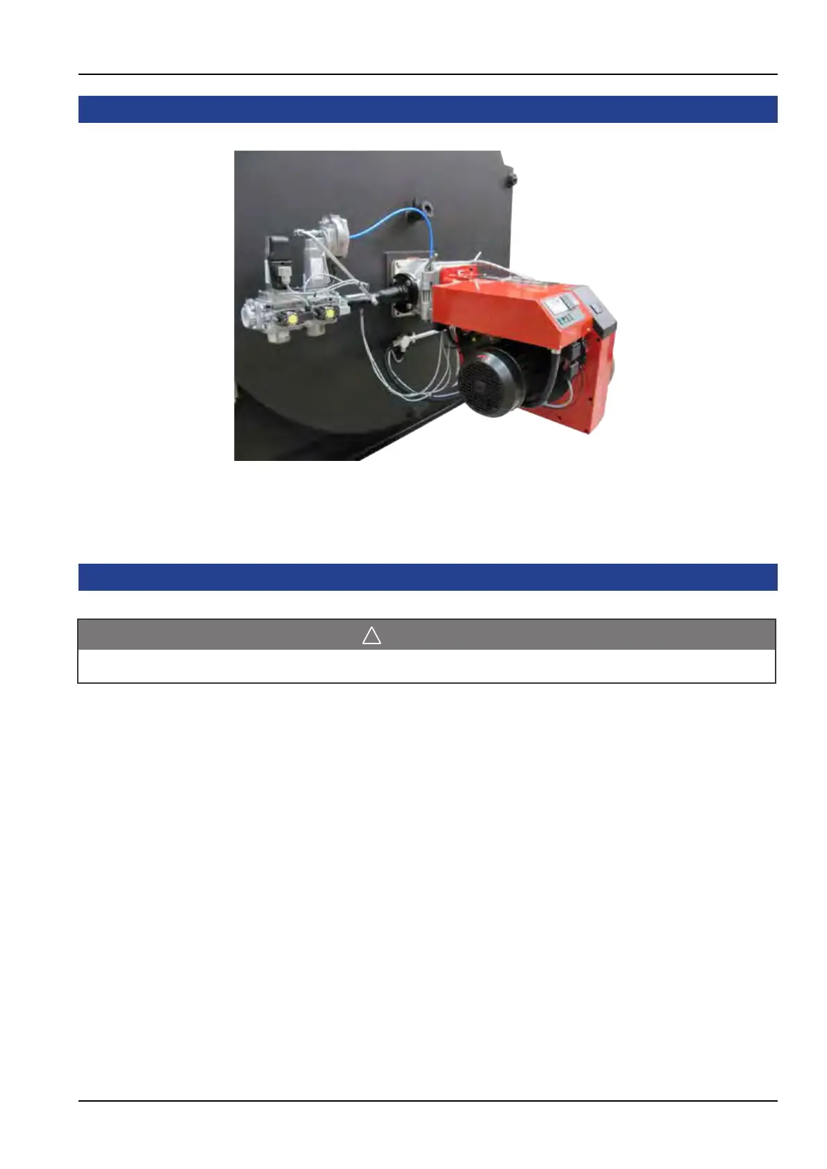
Figure. 11 - Dual Fuel Burner Installation
Note: Installation will change with the type of burner tted.
CAUTION
Anyelectricalworkshouldbeundertakenbyaqualiedelectriciantocurrentlocalregulations.