RB-RBC-IOMM-2015-1
Fulton Ltd
Page 64
APPENDIX - A
Automatic TDS Blowdown Systems
Technical Information
Sheet No. 30 Issue 3
Page 1 of 2
The purpose of an Automatic, Total Dissolved Solids (TDS) Control Blowdown System, is to control the TDS level
within the boiler around a set point. It is not a substitute for the main boiler blowdown, which must be used to
control suspended solids, and prevent the build-up of sludge in the bottom of the boiler. The daily testing of boiler
water level controls is a mandatory requirement as dened in the Health & Safety Executive Guidance Note BG01,
Arrangement 3.
The method of operation is to take a sample of the boiler water at pre-set timed intervals, pass the sample over an
electrode which measures water conductivity (which is proportional to TDS for a given water chemistry), and then
compares the result with the control value (normally 2000 ppm), which is set when the unit is commissioned.
If the sample value is higher than the control value, the blowdown solenoid valve opens in a series of pulses until
the measured value corresponds to, or is lower than, the set value. When this is achieved, blowdown nishes until
the next timed sample is taken when the process is repeated. Should the sample value be lower than the set value,
blowdown is deferred until the next timed sample.
For the system to function reliably, the control must be calibrated to a typical water sample that is representative
of the water conditions that are likely to prevail during normal running of the boiler and system. Conductivity and
as a consequence TDS, can vary signicantly with water chemistry. Changes in condensate return rates, alkalinity,
chemical dosage, and suspended solids can all affect the performance of an Automatic TDS Blowdown System.
Condensate return rates that vary greatly on a day to day basis can severely disrupt the reliability of the
conductivity measurement.
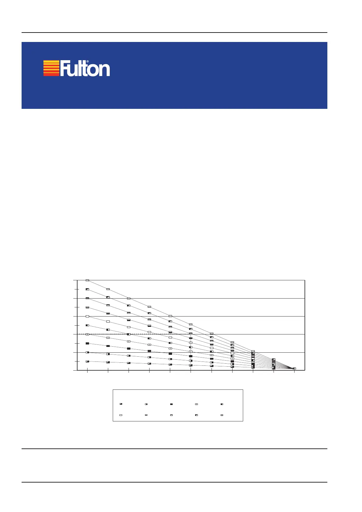
500
400
300
200
100
0
0 10 20 30 40 50 60 70 80 90 100
Feed water TDS at varying
condensate return rates
Condensate return(%)
Raw water TDS (ppm)
50
300
100
350
150
400
200
450
250
500
Feed water TDS (ppm)
e.g. A boiler with a 50% condensate return and a raw water TDS of 400 will have a boiler feed water TDS of 200 ppm.
Figure. 1 - TDS Graph 1