RB-RBC-IOMM-2015-1
Fulton Ltd
Page 12
INSTALLATION - 2
2.10.2 OIL SUPPLY
Oil-redboilersaresuppliedwitha
matched, automatic high/low oil burner
suitable for use with 35 SRNI fuel oil.
A single-pipe system can be used where
thesuctionisfullyooded,however,for
systemswhere‘lift’isrequired,itwillbe
necessary to install a two-pipe system.
For more details consult the burner
manufacturer’sinstructionmanual.
The following points should be observed:
a) Alwaysinstallanoillter.
b) Useexiblepipeworkforthenaloil
connections to the oil pump.
c) Fit isolating valves to the pump.
d) Ensure that the supply pipework is
sized to cause a minimum pressure
drop.
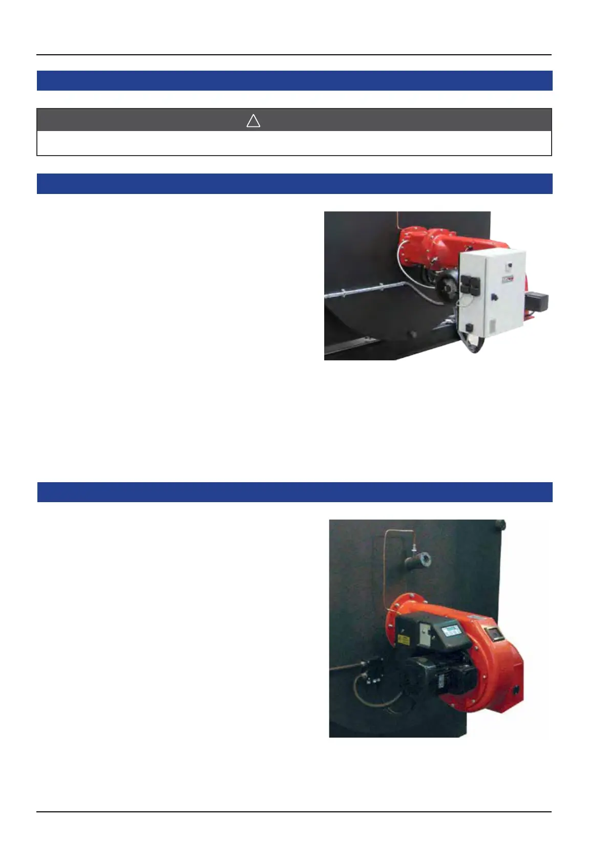
Figure. 10 - Oil Burner Installation
Note: Installation will change with the type of
burner tted.
2.10 FUEL SUPPLY
WARNING
Do not change the boiler fuel without consulting the boiler manufacturer.
2.10.1 GAS SUPPLY
The gas/pressure requirement varies
according to the burner size and the gas
train selected.
Verify that the type and pressure of the
gas available on the site is suitable for the
burnertted.
If the site gas pressure is too low, it will be
necessarytotagasboostersystem.
Consult Fulton Ltd if in doubt.
To minimise pressure drops, eliminate
all unnecessary bends and elbows in the
pipework between the gas meter and the
inlet to the gas train.
Ensure that a gas cock of the correct size
is installed as close as possible to the gas
train.
All gas pipework must be installed by
‘CompetentPersons’inaccordancewith
the gas regulations.
Figure. 9 - Gas Burner Installation
Note: Installation will change with the type of
burner tted.