RB-RBC-IOMM-2015-1
Fulton Ltd
Page 57
APPENDIX - A
Sales & Service: +44 (0) 117 977 2563
Telephone: +44 (0) 117 972 3322
Fax: +44 (0) 117 972 3358
E-mail: uk.sales.offi ce@fulton.com
Website: www.fulton.co.uk
TI109 ISSUE 4
Every effort is made to ensure accuracy at time of going to press. However as part of our policy of continual product improvement, we reserve the right to alter specifi cations without prior notice.
Fulton Ltd.
Broomhill Road, Bristol, BS4 4TU, England.
Specifi cation
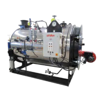
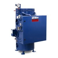
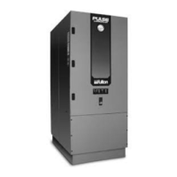
MODEL: RBC UNIT 600 750 1000 1250 1500 1850 2100 2500 3000
CE marked to PED, EMC, LVD & Machinery Directive, constructed to BS2790 as standard
(other code specifi cations available).
General
Steam Output F & A 100°C kg/h 957 1197 1596 1995 2393 2952 3350 3990 4787
kW Rating kW 600 750 1000 1250 1500 1850 2100 2500 3000
Operating Pressure barg 10.34 10.34 10.34 10.34 10.34 10.34 10.34 10.34 10.34
Weight
Shipping Weight (ex. burner) kg 4310 4710 5350 7280 7380 8870 8970 10600 12170
Operational Weight kg 5660 6160 6910 9566 9620 11758 11820 14020 16507
Water Content L 1350 1450 1560 2286 2240 2888 2850 3420 4337
Minimum Gas Pressures
Natural Gas Modulating mbar 15.7 15.5 30 45.7 57.3 66.4 54.5 66 60.9
Natural Gas On/Off mbar 15.7 15.5 30 45.7 57.3 66.4 54.5 66 60.9
LPG mbar 50 50 50 50 50 50 50 50 50
Firing Rate ****
Gas m
3
/h 67 84 112 140 168 208 236 281 337
Oil L/h 64 80 106 133 159 197 226 267 321
LPG/Propane m
3
/h 28 35 46 58 70 86 98 117 140
Ventilation Requirements for Combustion Purposes (Free Area)
Low Level Inlet cm
2
3660 4510 5923 7336 8851 10435 11678 13444 15716
High Level Outlet cm
2
1830 2255 2961 3668 4425 5217 5839 6722 7858
Electrical Requirements
FLC 400 V 3 ph 50 Hz A 6.2 7 7 8.4 8.4 8.4 10 12 12
FLC 230 V 1 ph 50 Hz A 7.8 9.1 9.1 11.5 11.5 11.5 14.2 17.6 17.6
Burner Fan, Light Oil Fired A 1.1 1.5 1.5 2.2 2.2 2.2 3 4 4
Burner Fan, Gas Fired A 1.1 1.5 1.5 2.2 2.2 2.2 3 4 4
Burner Fan, Dual Fuel A 1.1 1.5 1.5 2.2 2.2 2.2 3 4 4
Feedwater Pump A 1.1 1.5 1.5 2.2 2.2 2.2 3 4 4
Connection Sizes
All threads BSP. All fl anges to BS4504, PN16-A2 unless otherwise stated.
Steam Outlet (PN16) DN 65 65 65 100 100 100 100 125 125
Safety Valve Discharge (PN16) DN 40 40 50 50 50 65 65 80 80
Feedwater Inlet (PN16) DN 25 25 25 32 32 32 32 32 32
Feedwater Pump Inlet (BSP) DN 25 25 25 - - - - - -
Feedwater Pump Inlet (PN16) DN - - - 32 32 32 32 32 32
Blowdown, Boiler (PN16) DN 25 25 25 32 32 32 32 40 40
Blowdown, Water Level Gauge
(Sight Glass) (BSP)
DN 15 15 15 15 15 15 15 15 15
Blowdown, TDS (PN16) DN 25 25 25 25 25 25 25 25 25
Flue Outlet mm 250 300 300 350 400 450 450 500 550
Water Sample Outlet (PN16) DN 15 15 15 15 15 15 15 15 15
Gas Inlet, natural gas (BSPP) DN 40***** 40***** 40 40 40 - - - -
Gas Inlet, natural gas (PN16) DN - - 65***** - - 80 65 65 80
Oil Connection in. Flexible hoses provided 1/2 in. BSP all models.
Note:
**** Figures based on gross cv fi gures from DUKES report 2010.
***** Gas booster not fi tted.