Chapter 8. Q &A
8-1
Q1. Can the FAX-5 antenna unit be used with NX-700A and B?
It can be used in terms of electric characteristics. However, since the requirements
for the Type approval of NX-700A and B include the Antenna unit NX-7H, the
FAX-5 antenna cannot be used with NX-700A and B.
Q2. Can the NX-5 antenna unit be used with NX-700A and B?
No.
Since the requirements for the Type approval of NX-700A and B include the
Antenna unit NX-7H, the NX-5 antenna cannot be used with NX-700A and B.
NX-5 is an Antenna unit dedicated for reception on 518 kHz. If the Antenna unit of
NX-5 is used, the receiver sensitivity is reduced particularly on local frequency
4209.5 kHz.
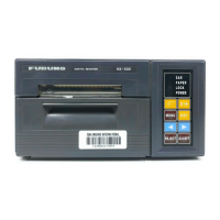
Q3. Give information on the specifications of a connectable printer. (5-13)
Serial printer: 9600 bps, 8 bit data, non parity, 1 bit stop-bit, Xon/Xoff, 32 Char/line
Q4. What part should the Nav data (GPS) be connected to? (2-5)
Connect the Nav data to #4(RD-A) and #5(RD-B) of J402 on NX-7001. Be sure to
make a connection to #3 (ISO GND).
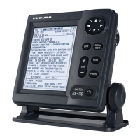
Q5. What is the length of the cable between the Display unit and
the Receiver unit? (1-2)
Communication between Display unit and Receiver units is achieved via RS-232C.
Since this cable includes the power supply line, the cable length differs according
to the specifications of the power supply. It is 3 m for +12 VDC power supply and
15 m for +24 VDC power supply.
Q6. When the NX-700A/B is used at an exhibition or presentation,
is it needed to connect the Antenna unit? (2-25)
It is NOT necessary. Operate it in the DEMO mode. To enter this mode, select ON
in “[MENU] -> Initialize1 -> Demo Mode”.
Q7. Is there any difference according to the input power (+12/24 VDC)? (3-9)
There is NO difference by the input power.
There is no need to change the fuse (2 A) on the RCV board of NX-7001. This fuse
is intended for protection against reverse connection.
Q8. The INS connection port is of the RS-485 type. How is the ON/OFF
setting of the terminating resistor performed? (3-6)
The setting is performed at J9 on the CPU board of the Display unit. The plug J9 is
inserted between #1 and #2, it is set as “With termination”. (Default setting)
Do not connect the INS I/O port to be connected to NX-700A and B in parallel
with other equipment and use it on its own. In this case, leave the setting of J9 at
default as “With termination”.
Chapter 8. Q & A

 Loading...