5.2 Connection
5-4
J401
(
25p D-sub connector
)
1 SD IN
14 RD OUT
RS-232C external printer signal
(For NX-700B only, NC signal for NX-700A)
2 TD-A
15 TD-B
IN
IEC61162-1/2: RS-485
(INS Data output)
3 RD-A
16 RD-B
OUT
IEC61162-1/2: RS-485
(GPS data/INS Data input)
4 Alarm-H
17 Alarm-C
IN
Photo MOS relay contact output for external alarm
(50 VDC / 0.5 A max.)
5 TEST TD-A
18 TEST TD-B
OUT RS-485
6 FRQ TD-A
19 FRQ TD-B
OUT RS-485
7 490 RD-A
20 490 RD-B
IN RS-485
8 518 RD-A
21 518 RD-B
IN RS-485
9 +12 VDC
22 0 V
IN
10 GND ISO
23, 11, 24 DC +
12, 25, 13 DC -
OUT +12 VDC to +24 VDC
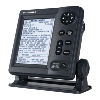
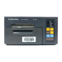
2. Display unit: NX-700A/B
The specifications of the input/output of [RECEIVER] port of the Display unit:
NX-700A incorporating a printer and the [RECEIVER] port of NX-700B including LCD
unit alone are same, although SD/RD signals of #1 and #14 pins of the [RECEIVER]
port on NX-700A are not connected.
Table 5.2.2 Specifications of Input/Output of Display unit
Pin No. Signal IN/OUT Specifications
1 SD OUT
14 RD IN
RS-232C external printer signal
(For NX-700B only, NC signal for NX-700A)
2 TD-A
15 TD-B
OUT
IEC61162-1/2: RS-485
(INS Data output)
3 RD-A
16 RD-B
IN
IEC61162-1/2: RS-485
(GPS data/INS Data input)
4 Alarm-H
17 Alarm-C
OUT
PhotoMOS relay contact output for external alarm
(50 VDC / 0.5 A max.)
5 TEST TD-A
18 TEST TD-B
OUT RS-485
6 FRQ TD-A
19 FRQ TD-B
OUT RS-485
7 490 RD-A
20 490 RD-B
IN RS-485
8 518 RD-A IN RS-485

 Loading...