106
6 Modifications to the basic vehicle
6.11 Brake systems
MITSUBISHI FUSO body/equipment mounting directives for FE Issue date: 20. 10. 2020
! Only print out complete sections from the current version
• Securely clamp brake lines with PVC coated
clamps or grommets to prevent vibrations when
the vehicle is running.
• The standard brake line clearances are shown in
the table below.
Unit: mm
• Brake lines should be laid along the inside web of
the side rail whenever possible. When they cross
over to the opposite side rail, they should be
positioned along the cross members.
Install the lines more than 10 mm away from bolts
and rivets.
• Make sure the brake fluid lines can be bled easily.
• Never clamp or tape electrical wires to the brake
lines, as this can cause corrosion of the line.
Maintain the clearances described in Section 4
"Clearance for the basic vehicle and bodies" É 4.4.
• The clearance between the brake lines
components should conform to the specifications
in Section 4 "Clearance for the basic vehicle and
bodies" É 4.4.
• Position the connection nut in a location where it
can be completely tightened without difficulty.
• Tighten the flare nuts to torque specified in
É 6.11.2. Do not tighten the flare nut any further if
oil leaks. Loosen the flare nut completely, adjust
the mating surfaces, re-thread the nut and then
tighten it completely.
• Never force or tighten any part with a wrench or
other tool if problems occur while installing brake
lines. Realign the brake lines so the mating
surfaces are correctly positioned, and then tighten
the flare nut. If possible, first gently thread the nuts
by hand, and then tighten them with the
designated flare nut wrench.
• Never install brake lines near the drive shaft or
other moving parts.
• Never change the installation location of the brake
hoses.
• When replacing the brake lines, do not use the fluid
which was drained.
Drain the fluid completely and replace with new
fluid.
• Install the brake lines so that they are protected
from damages caused by flying objects thrown up
by the tires.
• When it is necessary to protect brake lines against
possible damage as described above, install a
protective panel as shown below.
(a) Fabricate a protective panel which will not be
deformed by flying objects and come in contact
with the brake lines.
(b) Position and shape the protective panel
properly (for drain holes, etc.) so water will
drain freely.
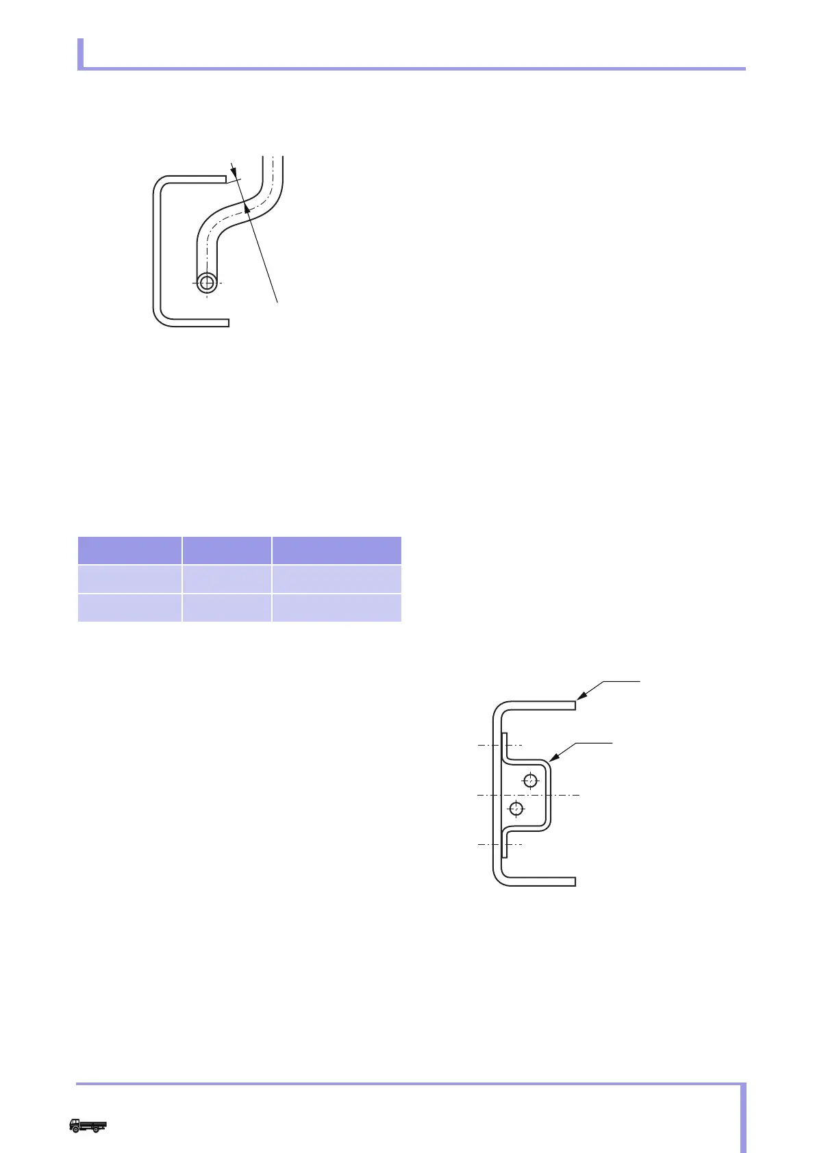
Fig. 5
Tube dia Clamp intervals
Straight tube 4.75-8 550 max.
Curved tube ↑ 400 max.
1 Sharp edges
2 15 mm min.
Example
Fig. 6