127
7 Construction of bodies
7.1 General
MITSUBISHI FUSO body/equipment mounting directives for FE Issue date: 20. 10. 2020
! Only print out complete sections from the current version
7.1.1 Body mounting methods
General
Correct calculation of load on the chassis frame
• If a mounting frame is used, the stress calculation
of the chassis frame must be conducted for beams
combined with the body to be mounted.
• The mounting frame must be fastened to the
chassis frame so firmly that the rear body weight
may be borne evenly by the combined chassis
frame and mounting frame.
7
10
1 2 3 4
5
6
9
8
N31.00-2218-00
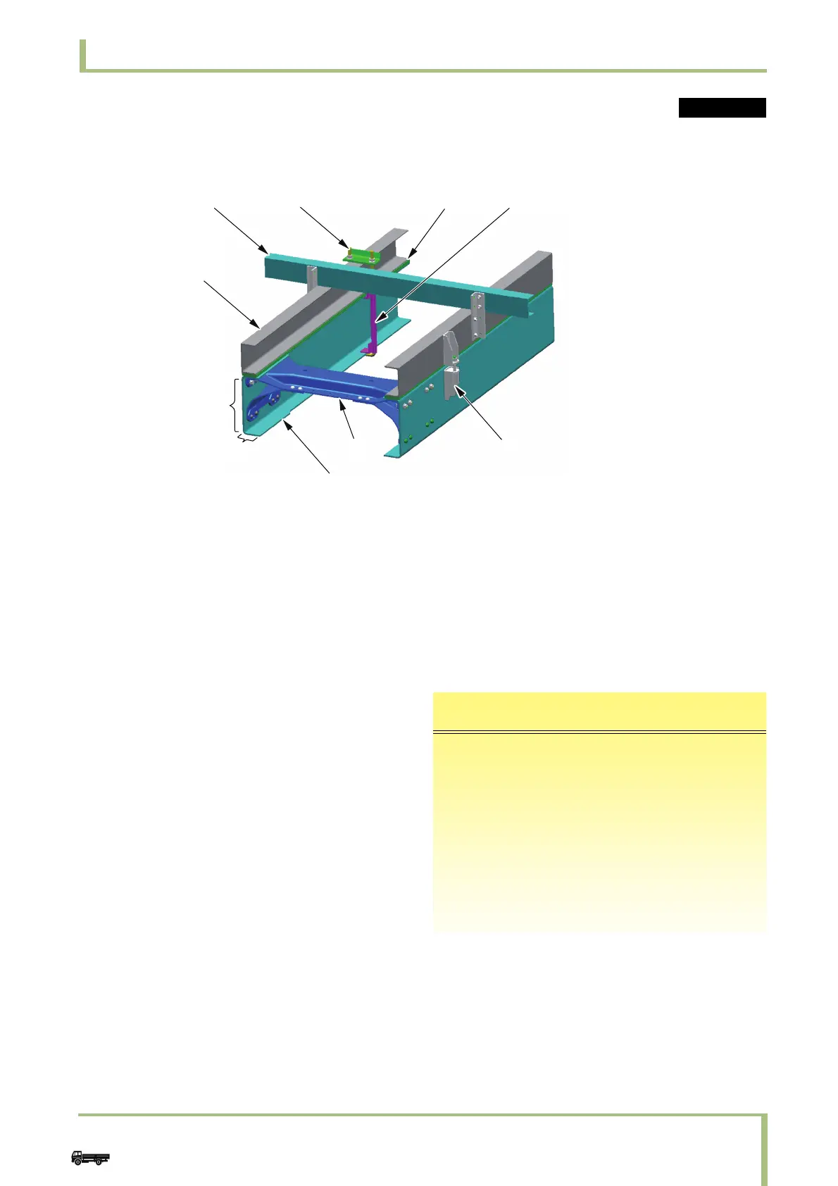
1 Cross sill
2U-bolt
3 Spacer (liner)
4 Spacer (for preventing deformation)
5 Mounting bracket
6 Cross member
7Chassis frame
8Flange
9Web
10 Mounting frame
i Additional information
• For the strength calculation of the chassis frame
and mounting frame, refer to "10.3 Weight
distribution table" É 10.3 and "10.5.2 Frame
section modulus" É 10.5.2.
• The frame stress should be less than the values
shown in the table below.
Common