147
8.1 Electrical system
8 Electrics/electronics
MITSUBISHI FUSO body/equipment mounting directives for FE Issue date: 20. 10. 2020
! Only print out complete sections from the current version
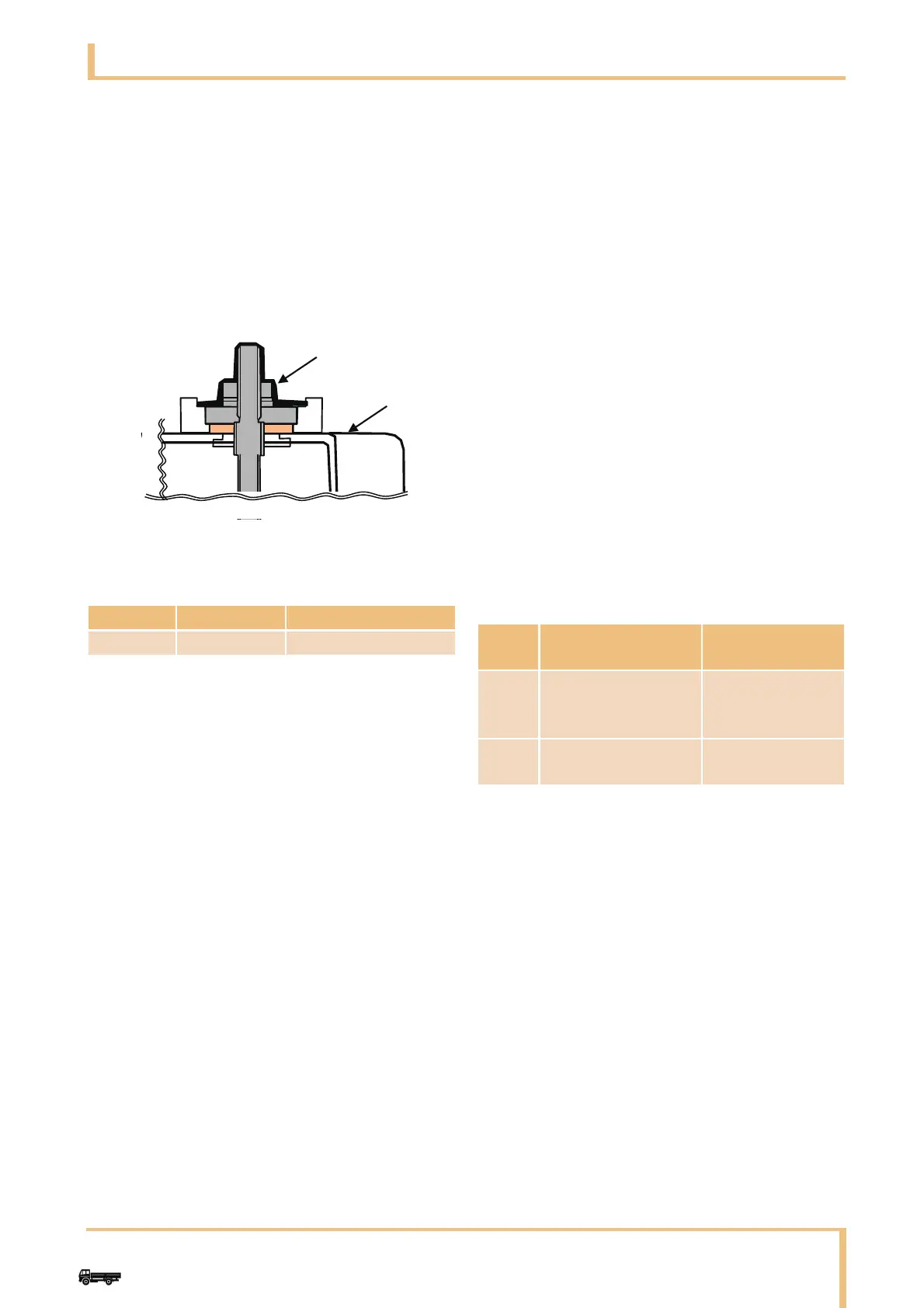
Apply silicone sealant to the illustrated
areas of the 12 V and 24 V terminals on the
battery equalizer and battery so that the
metal parts are completely covered. Remove
any air bubbles in the sealant, since they will
adversely affect the waterproofing effect.
After completing the application, leave it in
the horizontal position to dry (approx. 8
hours at 10°C and 50% humidity).
8.1.2 Signal detection and actuation
module-related parts
Cautions on Signal detection and Actuation
Module (SAM) (relay and fuse-integrated control
unit for body equipment)
The signal detection and actuation module is an
integrated unit with the control and power distribution
functions for electric parts of the cab and body
equipment.
(a) Before disconnecting the connected cables of
the signal detection and actuation module
control unit, set the starter switch of the vehicle
to OFF.
(b) Before performing welding to the chassis and
body, be sure to disconnect the signal detection
and actuation module control unit cables and
connectors. Use exteme care of spattering
(sparks, etc.) thrown on the harnesses during
the welding work.
Ground the welder near the weld.
(c) When cleaning inside the cab, take utmost care
not to splash the signal detection and actuation
module control unit (including relays, fuses and
connectors) with water.
(d) When removing the signal detection and
actuation module control unit from the vehicle,
set the starter switch of the vehicle to OFF, then
disconnect the harness from the battery
terminals and remove the connectors/nuts in
the following order. (To reinstall, reverse the
sequence of removal.)
• Disconnect the power line (connector
No. 9C, nut No. 10C) first.
• Disconnect the control unit connectors.
• Disconnect the ground line (connector
No. 8C) last.
• Bracket nuts (back of signal detection and
actuation module, M6 x 4)]
When installing the signal detection and
actuation module control unit to the vehicle,
tighten its nuts to the torques specified below.
Unit: N·m
(e) Relays and fuses should be carefully installed or
removed in/from the signal detection and
actuation module control unit one by one.
Name Part No. Remarks
SEALANT MS996198 Bond type
1 Silicon sealant
2 Battery equalizer
Nut
type
Torque Use
M6 4 to 6
(nominal value: 5.45)
To mount the
control unit to be
bracket
M8 10 to 15
(nominal value: 12.7)
To mount the
power line 10C