167
8.4 Power supply
8 Electrics/electronics
MITSUBISHI FUSO body/equipment mounting directives for FE Issue date: 20. 10. 2020
! Only print out complete sections from the current version
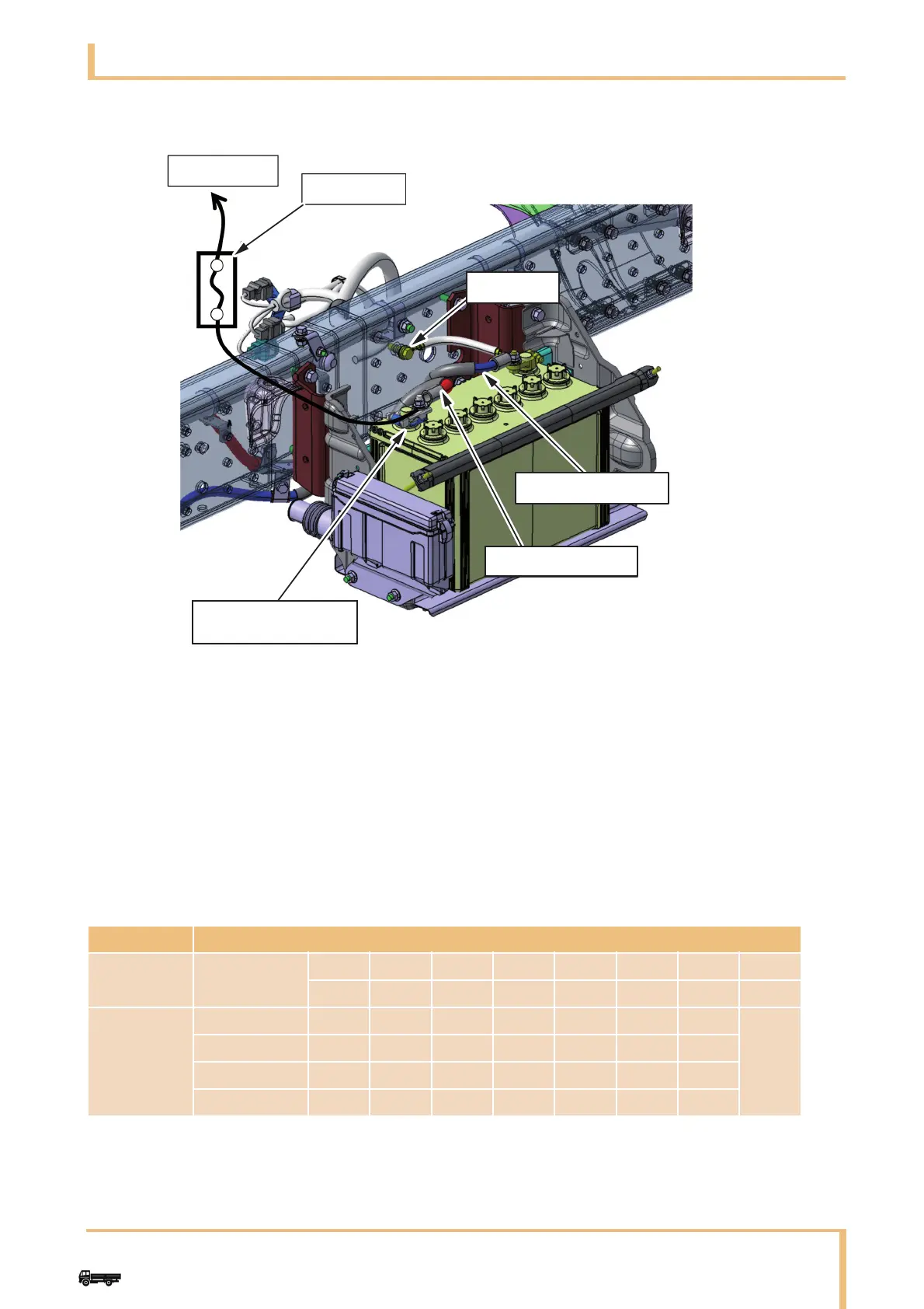
12 V
(f) Use a round flat terminal for the power supply terminal and jointly fasten it by using the fixing nut for
attaching the battery cable terminal.
Only one power supply terminal may be used.
Two or more additional terminals can be loosened, resulting in heat being generated or a short.
List of recommended combinations of fuse capacity and wire size
Note: Keep the continuous permissible current within 70 % of the fuse specifications value.
(E.g.) If the fuse used is 10 A:
10 × 0.7=7(A)
o A load of up to 7 A can be used.
v : Usable ì : Not usable
Fuse Wire size (mm
2
) [upper] and wire permissible current (A) [lower]
Type Specifications
0.3 0.5 0.85 1.25 2.0 3.0 5.0 (mm
2
)
11 14 18 23 31 42 57 (A)
Blade and
glass tube
5A v v v v v v v
7.5 A v v v v v v v
10 A ì v v v v v v
15 A ì ì v v v v v
1 Addition on the built body
2 Additional fuse etc.
3 Ground point
4Battery cable (–)
5Battery cable (+)
6 Terminal for taking power on built body side, M8 screw