180
8.7 Lighting
8 Electrics/electronics
MITSUBISHI FUSO body/equipment mounting directives for FE Issue date: 20. 10. 2020
! Only print out complete sections from the current version
Vertical adjustment: Turn screws A and B in that
sequence by equal amounts at a time.
Horizontal adjustment: Perform adjustment by turning
screw B.
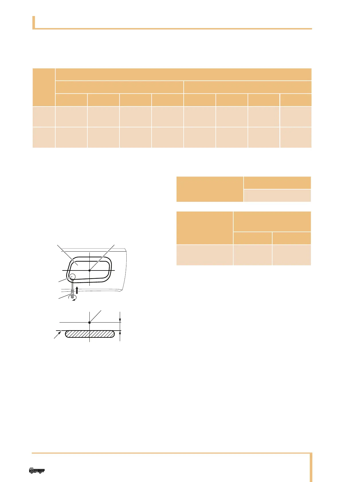
8.7.4 Fog lamp
After carrying out body-building, perform
re-adjustment of aiming.
Using the aiming adjustment gear, adjust the left and
right fog lamps to the correct optical axis.
Adjust the angle of the optical axis of the fog lamp so
that the light-dark boundary line is in the location
shown in the figure below.
Optical axis adjustment direction
Right headlamp Left headlamp
Up Down Left Right Up Down Left Right
Screw
A
Counter-
clockwise
Clock-
wise
Counter-
clockwise
Clock-
wise
Screw
B
Counter-
clockwise
Clock-
wise
Counter-c
lockwise
Clock-
wise
Counter-
clockwise
Clock-
wise
Clock-
wise
Counter-
clockwise
1Fog lamp
2Center of lamp
3 Aiming gear
4Screwdriver
5Vertical
6Lamp center
7 Cut-off position
8Horizontal
9 Cut-off line
Location of light-dark
boundary line
Adjustment value
1.5% max
Optical axis adjustment
direction
Up Down
Driver rotation
direction
Clockwise
Counter-
clockwise