www.gateway.com
61
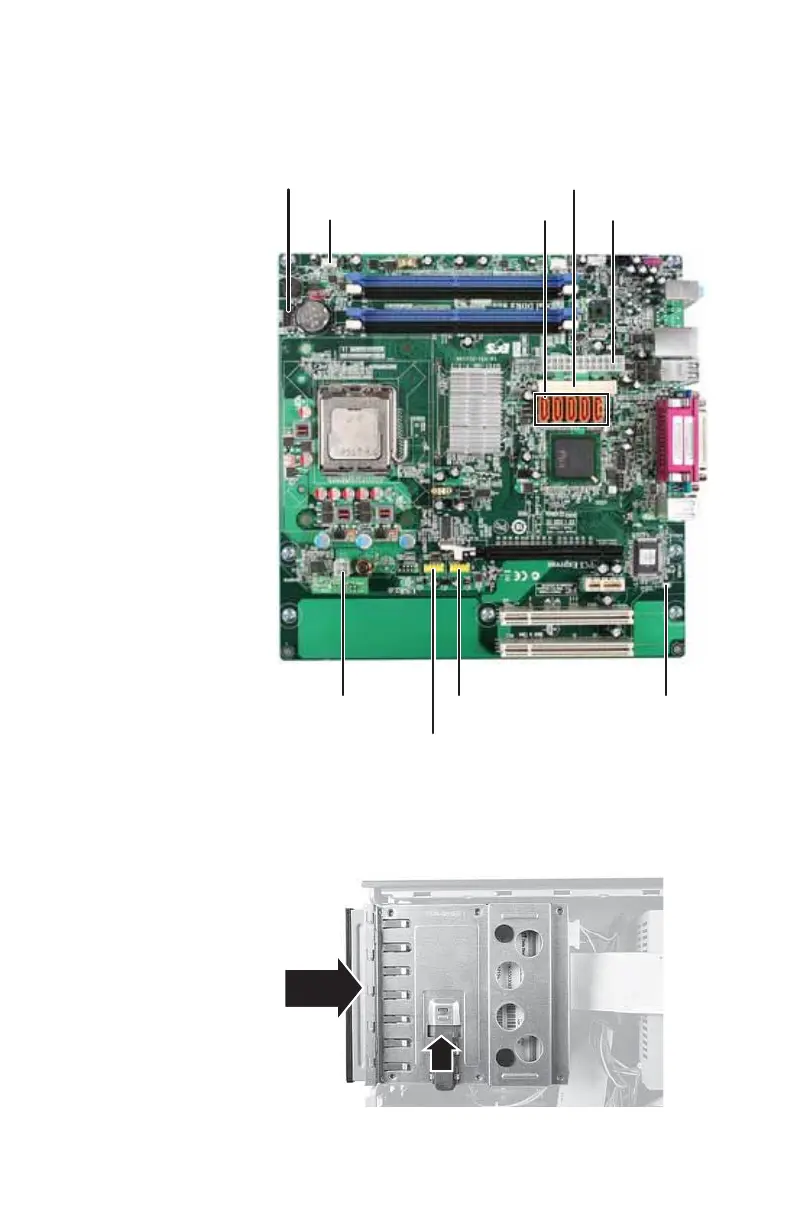
17 Connect the power and data cables to the new system
board using the notes you took previously, or use the
following graphic as a guide:
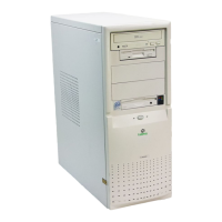
18 Replace the 5.25-inch component bay into the chassis.
19 Slide the 5.25-inch component into the bay, then push
up on the release latch to move it to the Lock position.
Front panel
Front (CPU) fan
Power (AUX)
Memory card reader
connector
USB header Chassis intrusion switch
SATA connectors Power (main)
IDE connector
8512732.book Page 61 Thursday, September 27, 2007 11:33 AM