Chapter 2: Installation
8 TruVision DVR 10 User Manual
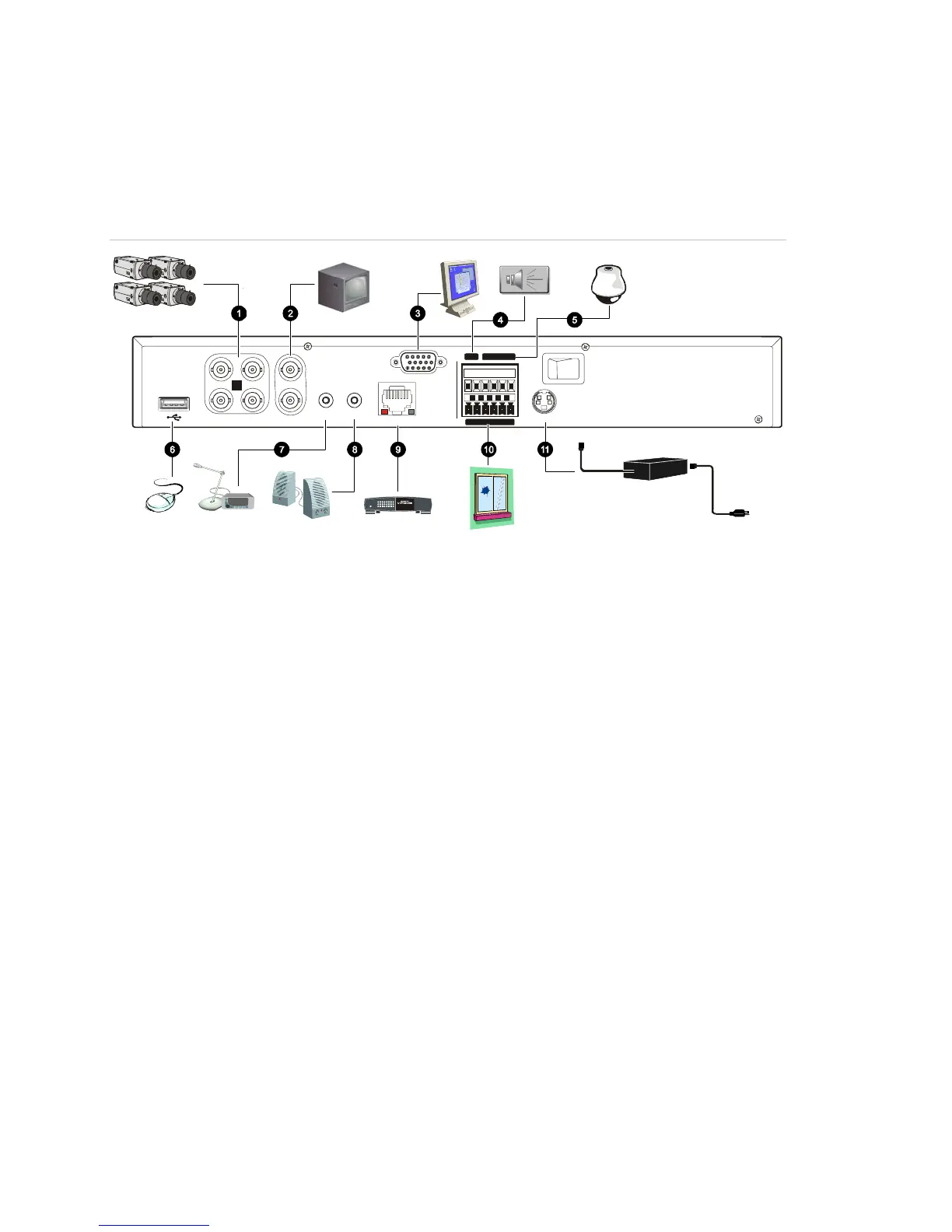
Connection diagram
Use Figure 2 below as a visual guide to connect the various peripherals to the TVR 10.
Figure 2: Rear panel connection diagram
13
42
VIN VOUT
1
2
AIN AOUT
ETHERNET
VGA
RS-485
ALARM IN
OUT
POWER
+12V
T+T-R+R-1 G
1234GG
Power
Link/Act
100
FD/Col
12345678
1. Connect up to four cameras
2. Connect up to two CCTV monitors (one for main,
two for spot)
3. Connect to a VGA monitor
4. Alarm output
5. Connect to a PTZ control
6. Connect to a USB mouse
7. Connect to audio input
8. Connect to speakers
9. Connect to network devices
10. Connect to alarm input cables
11. Connect to the power supply
 Loading...