1-6 Series 90-30 PLC Installation and Hardware Manual
–
August 2002 GFK-0356Q
1
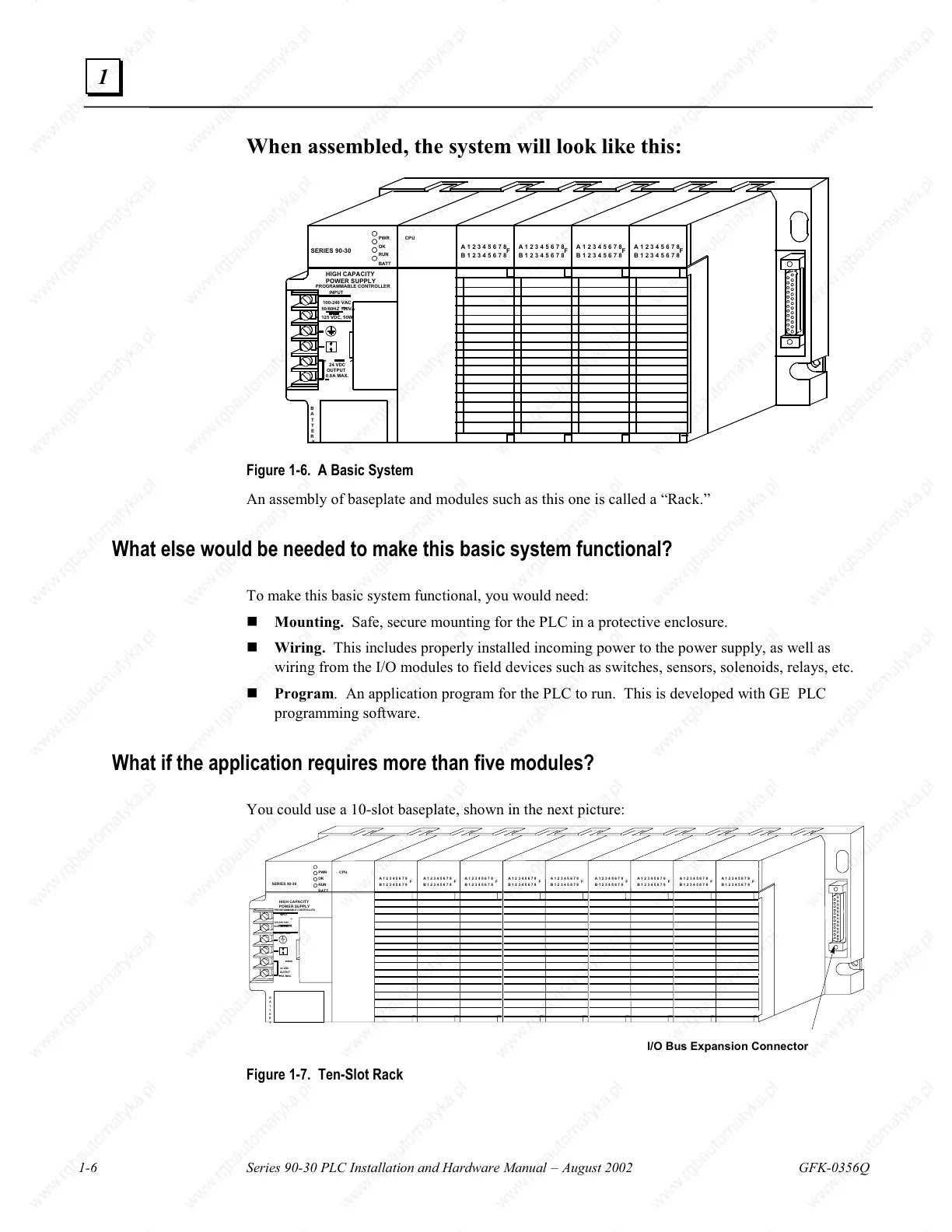
When assembled, the system will look like this:
0.8A MAX.
OUTPUT
HIGH CAPACITY
125 VDC, 50W
+
100-240 VAC
50/60HZ 100VA
24 VDC
INPUT
POWER SUPPLY
PROGRAMMABLE CONTROLLER
SERIES 90-30
~
PWR
OK
RUN
BATT
B
A
T
T
E
R
Y
A 1 2 3 4 5 6 7 8
F
B 1 2 3 4 5 6 7 8
A 1 2 3 4 5 6 7 8
F
B 1 2 3 4 5 6 7 8
A 1 2 3 4 5 6 7 8
F
B 1 2 3 4 5 6 7 8
A 1 2 3 4 5 6 7 8
F
B 1 2 3 4 5 6 7 8
CPU
Figure 1-6. A Basic System
An assembly of baseplate and modules such as this one is called a “Rack.”
What else would be needed to make this basic system functional?
To make this basic system functional, you would need:
Mounting. Safe, secure mounting for the PLC in a protective enclosure.
Wiring. This includes properly installed incoming power to the power supply, as well as
wiring from the I/O modules to field devices such as switches, sensors, solenoids, relays, etc.
Program. An application program for the PLC to run. This is developed with GE PLC
programming software.
What if the application requires more than five modules?
You could use a 10-slot baseplate, shown in the next picture:
HIGH CAPACITY
125 V DC, 50W
+
100- 240 VAC
50/60H Z 100V A
24 V DC
OUTPUT
0.8A MAX.
INPUT
POWER SUPPLY
PROGRAMMABLE CONTROLLER
SERIES 90-30
~
B
A
T
T
E
R
Y
PWR
OK
RUN
BATT
A 1 2 3 4 5 6 7 8
F
B 1 2 3 4 5 6 7 8
A 1 2 3 4 5 6 7 8
F
B 1 2 3 4 5 6 7 8
A 1 2 3 4 5 6 7 8
F
B 1 2 3 4 5 6 7 8
A 1 2 3 4 5 6 7 8
F
B 1 2 3 4 5 6 7 8
A 1 2 3 4 5 6 7 8
F
B 1 2 3 4 5 6 7 8
A 1 2 3 4 5 6 7 8
F
B 1 2 3 4 5 6 7 8
A 1 2 3 4 5 6 7 8
F
B 1 2 3 4 5 6 7 8
A 1 2 3 4 5 6 7 8
F
B 1 2 3 4 5 6 7 8
A 1 2 3 4 5 6 7 8
F
B 1 2 3 4 5 6 7 8
CPU
I/O Bus Expansion Connector
Figure 1-7. Ten-Slot Rack

 Loading...


