System Design and Layout
GFK-0356Q Chapter 12 System Design 12-11
12
Number of Modules Per Series 90-30 PLC System
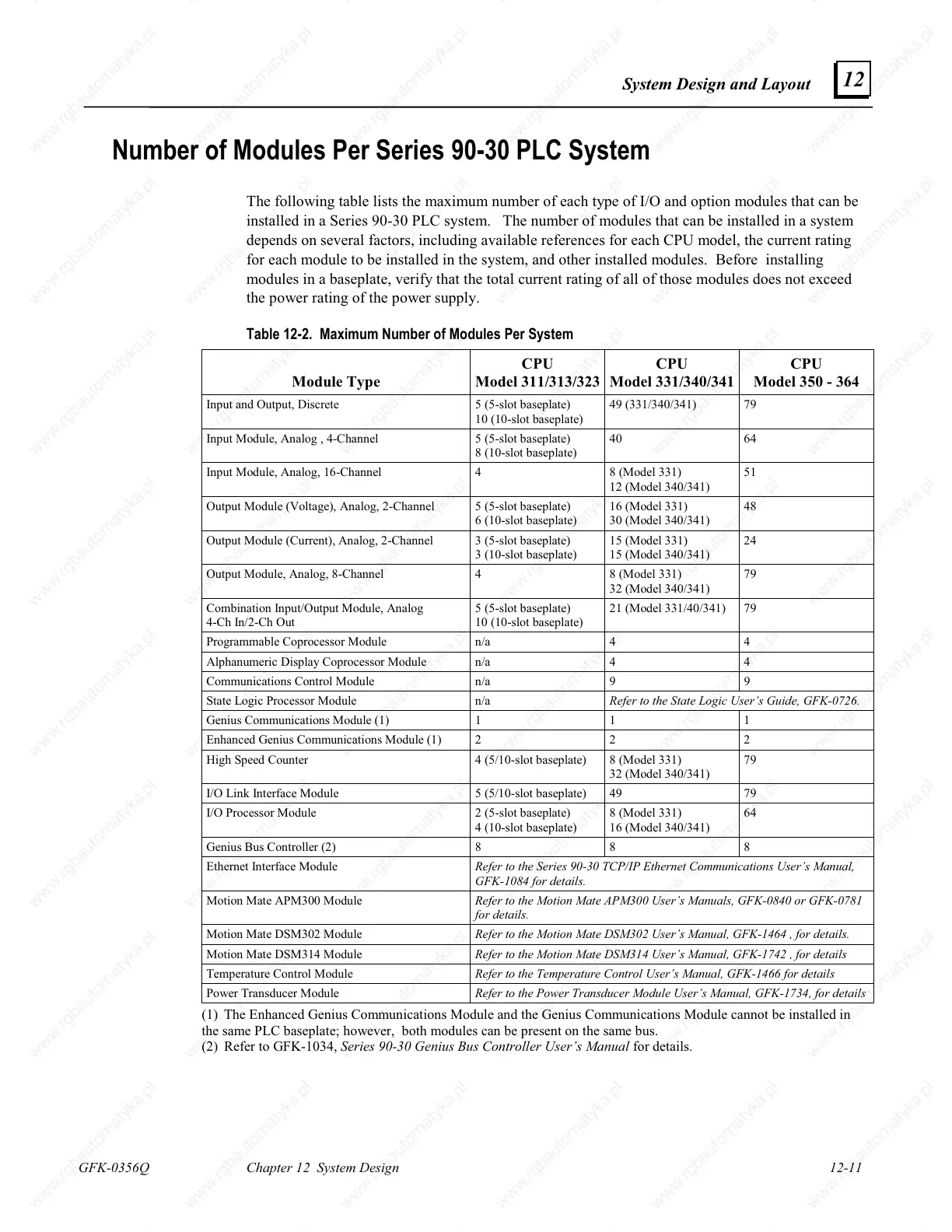
The following table lists the maximum number of each type of I/O and option modules that can be
installed in a Series 90-30 PLC system. The number of modules that can be installed in a system
depends on several factors, including available references for each CPU model, the current rating
for each module to be installed in the system, and other installed modules. Before installing
modules in a baseplate, verify that the total current rating of all of those modules does not exceed
the power rating of the power supply.
Table 12-2. Maximum Number of Modules Per System
Module Type
CPU
Model 311/313/323
CPU
Model 331/340/341
CPU
Model 350 - 364
Input and Output, Discrete 5 (5-slot baseplate)
10 (10-slot baseplate)
49 (331/340/341) 79
Input Module, Analog , 4-Channel 5 (5-slot baseplate)
8 (10-slot baseplate)
40 64
Input Module, Analog, 16-Channel 4 8 (Model 331)
12 (Model 340/341)
51
Output Module (Voltage), Analog, 2-Channel
5 (5-slot baseplate)
6 (10-slot baseplate)
16 (Model 331)
30 (Model 340/341)
48
Output Module (Current), Analog, 2-Channel 3 (5-slot baseplate)
3 (10-slot baseplate)
15 (Model 331)
15 (Model 340/341)
24
Output Module, Analog, 8-Channel 4 8 (Model 331)
32 (Model 340/341)
79
Combination Input/Output Module, Analog
4-Ch In/2-Ch Out
5 (5-slot baseplate)
10 (10-slot baseplate)
21 (Model 331/40/341) 79
Programmable Coprocessor Module n/a 4 4
Alphanumeric Display Coprocessor Module n/a 4 4
Communications Control Module n/a 9 9
State Logic Processor Module n/a
Refer to the State Logic User’s Guide, GFK-0726.
Genius Communications Module (1) 1 1 1
Enhanced Genius Communications Module (1) 2 2 2
High Speed Counter 4 (5/10-slot baseplate) 8 (Model 331)
32 (Model 340/341)
79
I/O Link Interface Module 5 (5/10-slot baseplate) 49 79
I/O Processor Module 2 (5-slot baseplate)
4 (10-slot baseplate)
8 (Model 331)
16 (Model 340/341)
64
Genius Bus Controller (2) 8 8 8
Ethernet Interface Module
Refer to the Series 90-30 TCP/IP Ethernet Communications User’s Manual,
GFK-1084 for details.
Motion Mate APM300 Module
Refer to the Motion Mate APM300 User’s Manuals, GFK-0840 or GFK-0781
for details.
Motion Mate DSM302 Module
Refer to the Motion Mate DSM302 User’s Manual, GFK-1464 , for details.
Motion Mate DSM314 Module
Refer to the Motion Mate DSM314 User’s Manual, GFK-1742 , for details
Temperature Control Module
Refer to the Temperature Control User’s Manual, GFK-1466 for details
Power Transducer Module
Refer to the Power Transducer Module User’s Manual, GFK-1734, for details
(1) The Enhanced Genius Communications Module and the Genius Communications Module cannot be installed in
the same PLC baseplate; however, both modules can be present on the same bus.
(2) Refer to GFK-1034,
Series 90-30 Genius Bus Controller User’s Manual
for details.

 Loading...


