4-6 Series 90-30 PLC Installation and Hardware Manual
–
August 2002 GFK-0356Q
4
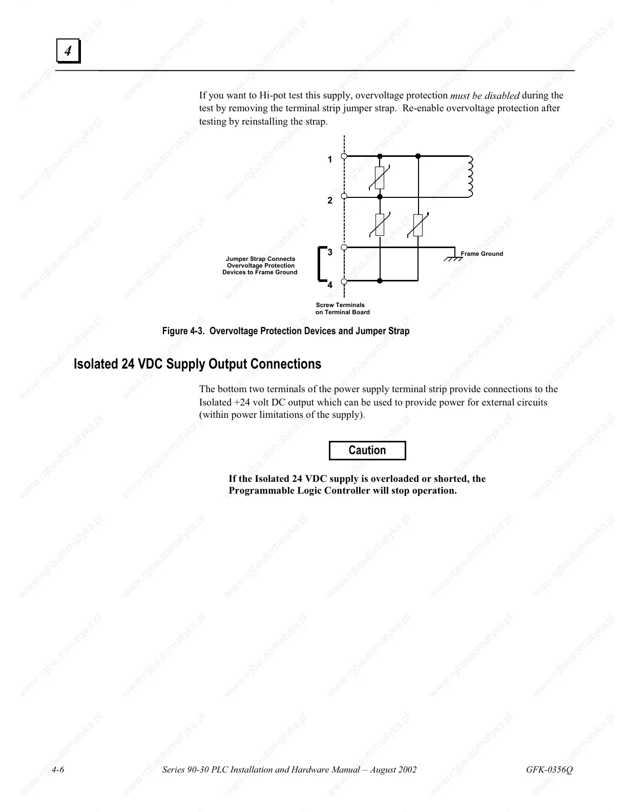
If you want to Hi-pot test this supply, overvoltage protection
must be disabled
during the
test by removing the terminal strip jumper strap. Re-enable overvoltage protection after
testing by reinstalling the strap.
1
2
3
4
Jumper Strap Connects
Overvoltage Protection
Devices to Frame Ground
Screw Terminals
on Terminal Board
Frame Ground
Figure 4-3. Overvoltage Protection Devices and Jumper Strap
Isolated 24 VDC Supply Output Connections
The bottom two terminals of the power supply terminal strip provide connections to the
Isolated +24 volt DC output which can be used to provide power for external circuits
(within power limitations of the supply).
Caution
If the Isolated 24 VDC supply is overloaded or shorted, the
Programmable Logic Controller will stop operation.

 Loading...


