4-8 Series 90-30 PLC Installation and Hardware Manual
–
August 2002 GFK-0356Q
4
Table 4-7. Specifications for IC693PWR322 Power Supply
Nominal Rated Voltage
Input Voltage Range
Start
Run
24 or 48 VDC
2 to 56 VDC
8 to 56 VDC
Input Power
50 watts maximum at full load
Inrush Current
4A peak, 00 ms maximum
Output Power
5 VDC: 5 watts maximum
24 VDC Relay: 5 watts maximum
24 VDC Isolated: 20 watts maximum
NOTE: 30 watts maximum total (all three outputs)
Output Voltage
5 VDC: 5.0 VDC to 5.2 VDC (5. VDC nominal)
24 VDC Relay: 24 to 28 VDC
24 VDC Isolated: 2.5 VDC to 28 VDC
Protective Limits
Overvoltage:
Overcurrent;
5 VDC output: 6.4 to 7 V
5 VDC output: 4 A maximum
Holdup Time:
4 ms minimum
Standards
Refer to data sheet, GFK-0867B, or later version for
product standards, and general specifications.
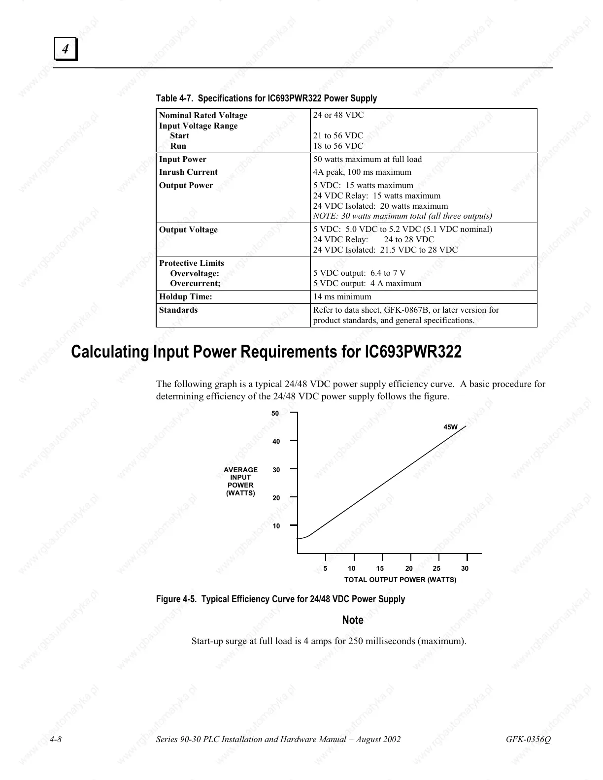
Calculating Input Power Requirements for IC693PWR322
The following graph is a typical 24/48 VDC power supply efficiency curve. A basic procedure for
determining efficiency of the 24/48 VDC power supply follows the figure.
51015 2530
VERAGE
INPUT
POWER
(WATTS)
TOTAL OUTPUT POWER (WATTS)
50
20
10
20
30
40
45W
Figure 4-5. Typical Efficiency Curve for 24/48 VDC Power Supply
Note
Start-up surge at full load is 4 amps for 250 milliseconds (maximum).

 Loading...


