1-2 Series 90-30 PLC Installation and Hardware Manual
–
August 2002 GFK-0356Q
1
CPUs
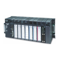
The CPU is the manager of the PLC. Every PLC system must have one. A CPU uses the
instructions in its firmware and application program to direct the PLC’s operation and to monitor
the system to make sure there are no basic faults. Some Series 90-30 CPUs are built into
baseplates, but most are contained in plug-in modules. In some cases, the CPU resides in a
Personal Computer using a Personal Computer Interface Card that interfaces to Series 90-30 Input,
Output, and Option modules.
Input and Output (I/O) Modules
These modules enable the PLC to interface with input and output field devices such as switches,
sensors, relays, and solenoids. They are available in both discrete and analog types.
Option Modules
These modules extend the capability of the PLC beyond the basic functions. These provide such
things as communications and networking options, motion control, high speed counting,
temperature control, interfacing to operator interface stations, etc.
Cables
These connect the PLC components together or to other systems. Many standard prefabricated
cables are available from
GE . They are primarily used to:
Interconnect baseplates
Connect a programmer to the CPU or to an option module
Connect option modules to field devices or other systems.
Assembling a Basic Series 90-30 PLC System
Let’s assemble, on paper, a basic system using the following components:
Baseplate
Power Supply module
CPU module
Some I/O modules
We’ll start with the baseplate. To keep it simple, we’ll use a 5-slot size. Note that a 5-slot
baseplate actually has six slots, but the power supply slot is not numbered. Note also, that this
baseplate has a CPU slot, which is slot number 1, and it has an expansion connector on the right
end, which is used for connecting to another baseplate if the system has more than one baseplate.

 Loading...