Cables
GFK-0356Q Chapter 10 Cables 10-67
10
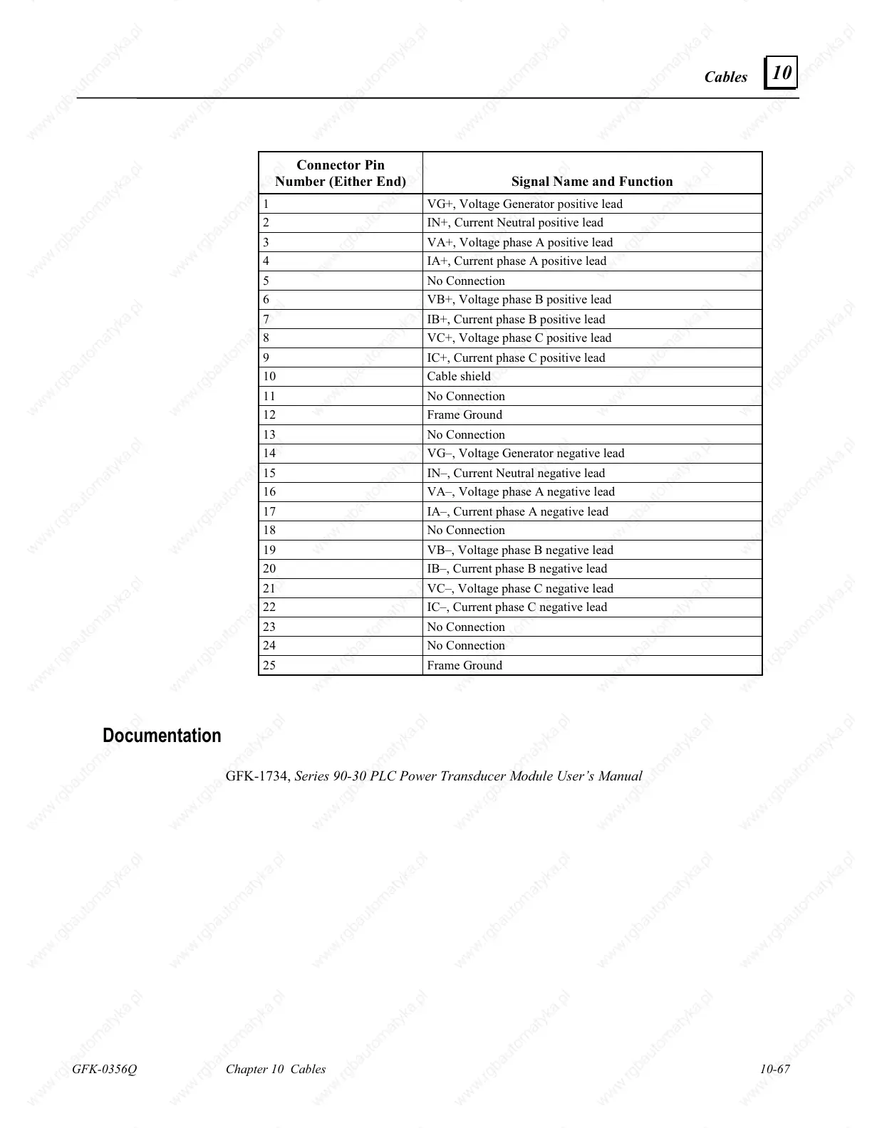
Connector Pin
Number (Either End) Signal Name and Function
1 VG+, Voltage Generator positive lead
2 IN+, Current Neutral positive lead
3 VA+, Voltage phase A positive lead
4 IA+, Current phase A positive lead
5 No Connection
6 VB+, Voltage phase B positive lead
7 IB+, Current phase B positive lead
8 VC+, Voltage phase C positive lead
9 IC+, Current phase C positive lead
10 Cable shield
11 No Connection
12 Frame Ground
13 No Connection
14 VG–, Voltage Generator negative lead
15 IN–, Current Neutral negative lead
16 VA–, Voltage phase A negative lead
17 IA–, Current phase A negative lead
18 No Connection
19 VB–, Voltage phase B negative lead
20 IB–, Current phase B negative lead
21 VC–, Voltage phase C negative lead
22 IC–, Current phase C negative lead
23 No Connection
24 No Connection
25 Frame Ground
Documentation
GFK-1734, Series 90-30 PLC Power Transducer Module User’s Manual

 Loading...


