10-8 Series 90-30 PLC Installation and Hardware Manual – August 2002 GFK-0356Q
10
IC647CBL704
Workstation Interface to Series 90 CPU (SNP Port) Cable
(Includes Instructions on Building Custom Length Cables)
Function of cable
The serial Work Station Interface cable has a 15-pin D connector on one end and a 37-pin D
connector on the other end. This cable connects the CPUs serial port to the Work station Interface
board installed in the programming computer through an isolated shielded, twisted pair.
Cable Specifications
Cable Length 10 feet (3 meters)
Connectors
CPU Side
Programmer Side
15-pin male, D-subminiature type with M3 screws and AMP hood 207908-4, or
equivalent
37-pin male, D-subminiature type with 4-40 screws and AMP hood 1-207908-0, or
equivalent
Hardware Kit AMP 207871-1. Kit includes two metric screws and two screw clips.
Cable Type
24 AWG (.21 mm
2
), 30V computer grade. Extra flexible construction
recommended for short lengths.
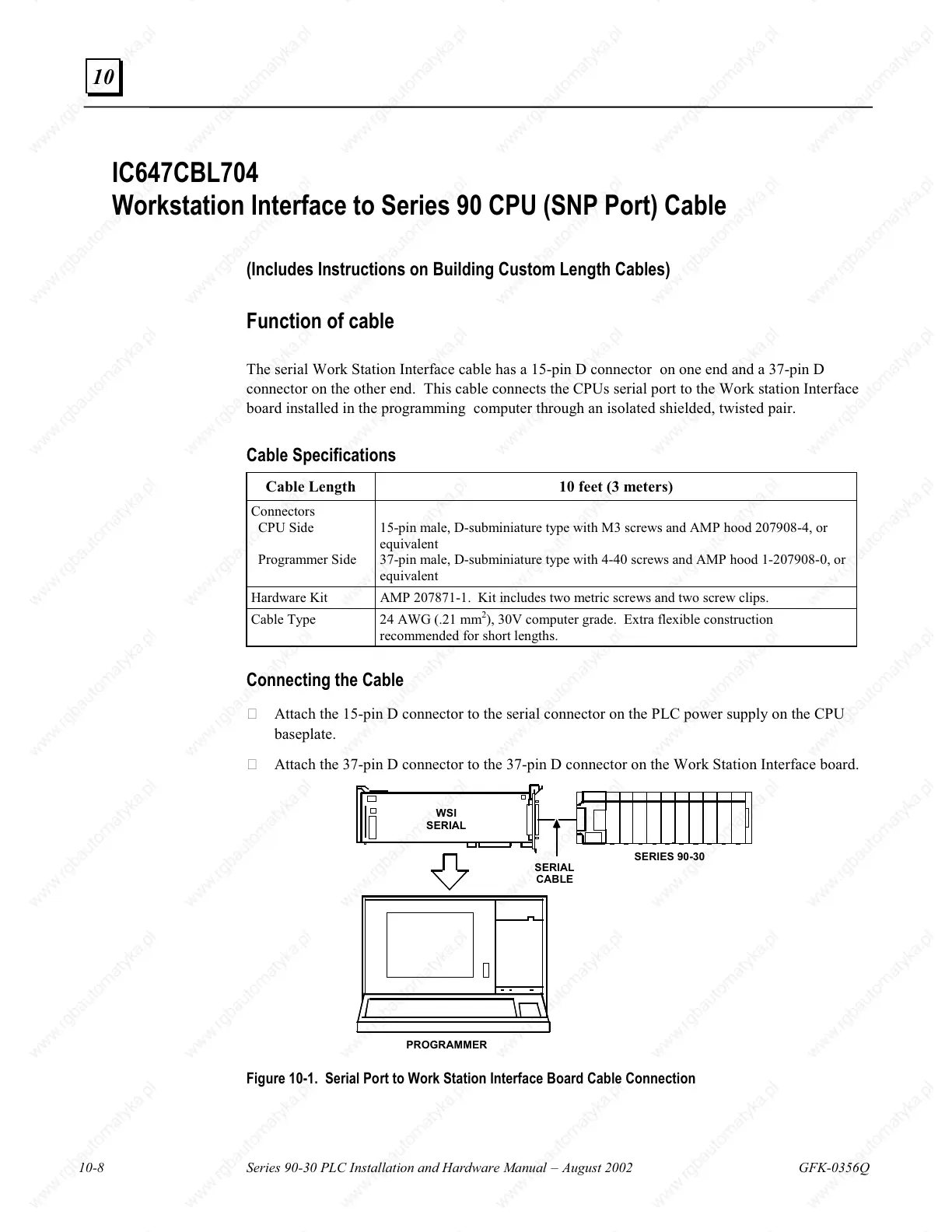
Connecting the Cable
Attach the 15-pin D connector to the serial connector on the PLC power supply on the CPU
baseplate.
Attach the 37-pin D connector to the 37-pin D connector on the Work Station Interface board.
WSI
SERIAL
SERIAL
CABLE
PROGRAMMER
SERIES 90-30
Figure 10-1. Serial Port to Work Station Interface Board Cable Connection

 Loading...


