Cables
GFK-0356Q Chapter 10 Cables 10-9
10
Building Custom Length Cables
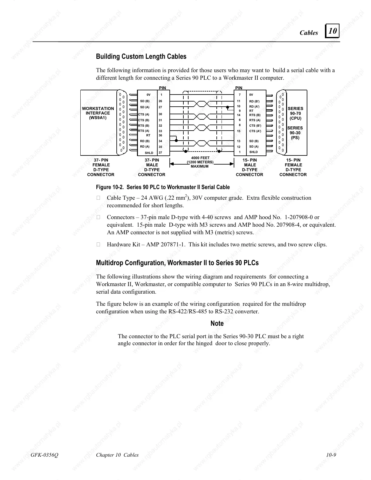
The following information is provided for those users who may want to build a serial cable with a
different length for connecting a Series 90 PLC to a Workmaster II computer.
PINPIN
SERIES
90-70
(CPU)
SERIES
90-30
(PS)
WORKSTATION
INTERFACE
(WS9A1)
SHLD
SHLD
15- PIN
MALE
D-TYPE
CONNECTOR
15- PIN
FEMALE
D-TYPE
CONNECTOR
37- PIN
MALE
D-TYPE
CONNECTOR
37- PIN
FEMALE
D-TYPE
CONNECTOR
0V
SD (B)
SD (A)
CTS (A)
CTS (B)
RTS (B)
RTS (A)
RD (B)
RD (A)
1
26
27
30
31
32
34
35
37
7
11
10
14
6
8
15
13
1
12
9
36RT
33
0V
RD (B')
RD (A')
RTS (B)
RTS (A)
CTS (B')
CTS (A')
SD (B)
SD (A)
RT
4000 FEET
(1200 METERS)
MAXIMUM
Figure 10-2. Series 90 PLC to Workmaster II Serial Cable
Cable Type – 24 AWG (.22 mm
2
), 30V computer grade. Extra flexible construction
recommended for short lengths.
Connectors – 37-pin male D-type with 4-40 screws and AMP hood No. 1-207908-0 or
equivalent. 15-pin male D-type with M3 screws and AMP hood No. 207908-4, or equivalent.
An AMP connector is not supplied with M3 (metric) screws.
Hardware Kit – AMP 207871-1. This kit includes two metric screws, and two screw clips.
Multidrop Configuration, Workmaster II to Series 90 PLCs
The following illustrations show the wiring diagram and requirements for connecting a
Workmaster II, Workmaster, or compatible computer to Series 90 PLCs in an 8-wire multidrop,
serial data configuration.
The figure below is an example of the wiring configuration required for the multidrop
configuration when using the RS-422/RS-485 to RS-232 converter.
Note
The connector to the PLC serial port in the Series 90-30 PLC must be a right
angle connector in order for the hinged door to close properly.

 Loading...


