PanaFlow™ LC User’s Manual 115
Appendix B. Using the Clamping Fixtures
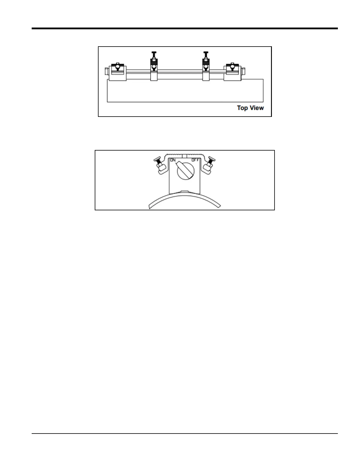
Figure 113: MCF Even Traverse Installation, Step 5
6. Turn the switches on both magnets to the
ON position.
Figure 114: MCF Even Traverse Installation, Step 6
Proceed to the section on mounting the transducers later in this chapter.
B.3.2 Odd number of-traverse method
Note: The instructions in this section can also be used for a multiple-traverse method. However, you must use
an
ODD number of traverses. The distance the signal travels from one side of the pipe wall to the
opposite side of the pipe wall is considered one traverse. For installations with more than one traverse,
contact BHGE for assistance.
The odd traverse MCF consists of two sub-assemblies. Each subassembly is made up of one adjustable
transducer block, two magnetic blocks and two connecting rods. The two sub-assemblies must be installed
on opposite sides of the pipe. To install the MCF in an odd traverse configuration, complete the following
steps:
1. Choose a location for the installation that has at least 10 pipe diameters of straight, undisturbed flow
upstream and at least 5 pipe diameters of straight, undisturbed flow downstream from the
measurement point.
2. Prepare the pipe where you intend to place the GCF by making sure it is clean and free of loose
material. Sanding, though usually not required, may be necessary to remove any high spots. However,
be careful to preserve the original curvature of the pipe.
3. Use a level to find the top of the pipe and then draw a line parallel to the centerline of the pipe.

 Loading...


