Chapter 2. Installation
22 PanaFlow™ LC User’s Manual
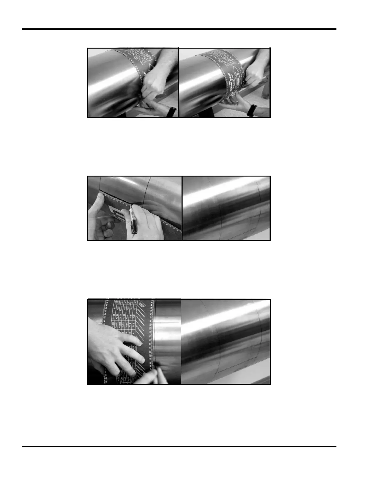
Figure 29: Marking Circumferential Lines on the Pipe
3. Line up the zero scale of the layout tape at the desired location of the first transducer. (For a typical
installation, this point will be the 3 o’clock position on a horizontal pipe.) Mark each of the two
circumferential lines at the zero point. Connect each of these marks using a straight edge (for
example, the edge of the layout tape) as shown in Figure 30 below.
Figure 30: Marking the 3 o’Clock Position
4. To find the coinciding point on the opposite side of the pipe (180° away from each other), divide the
measured circumference by 2 and measure this distance along the circumferential lines from the
zero point, as shown in Figure 31 below. Place marks on both sides of the circumferential lines made
with the layout wrap and connect the marks.
Figure 31: Marking the 9 o’Clock Position
Make sure to take the 180° point measurement from both over the top of the pipe and under the bottom of
the pipe (on a horizontal pipe) to ensure reciprocity of the installation. Figure 32 below shows the
appropriate way to measure the 180° point.

 Loading...


