4-24 C70 CAPACITOR BANK PROTECTION AND CONTROL SYSTEM – INSTRUCTION MANUAL
FRONT PANEL INTERFACE CHAPTER 4: INTERFACES
4
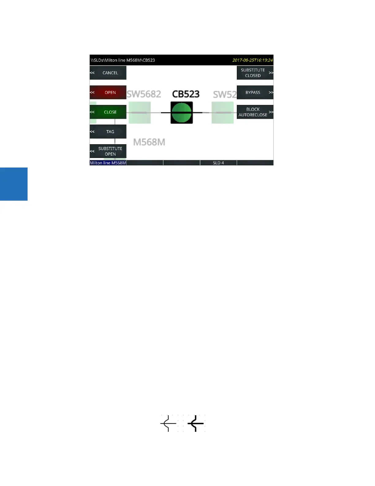
Figure 4-29: Pushbuttons to control the breaker
Press the pushbutton to close the breaker, confirming the action at the prompt.
In this diagram, the two circuit breakers have hard-coded actions available to them. No action is possible on the switches.
Note the USER PB 9 and 10 entries in the earlier figure. As outlined later, these are activated by clicking the PB icon on the
software toolbar. These two pushbuttons can be configured under Settings > Product Setup > User-Programmable
Pushbuttons.
Single-line diagram editor use
Start the application in the EnerVista software under Settings > Product Setup > Graphical Panel > Single Line Diagram
Editor.
The following buttons display at the top of the window:
• Save — Updates the connected device if online or the open setting file if offline with changes made
• Restore — Undoes changes that have not been saved
• Load — Opens single-line diagram files, which replaces one or all five windows with that in the file selected
• Store — Saves all five single-line diagrams as a .mif file
On the right side of the window is a toolbox containing the components that can be added to the window. These include
line, breaker, disconnect, metering value, status value, text, and miscellaneous power system elements. To create the
single-line diagram, click the symbol, then click in the window. Once in the window, the component can be positioned and
its properties modified. When using the pointing device to position a component, the component can snap to the nearest
snap point. Snap points are in a 4 x 4 rectangular grid. The keyboard arrow keys move the selected component(s) in one
pixel increments when snap locations are inadequate. Multiple components can be selected and moved or deleted as a
group, or copied and pasted to another location. Right- or double-clicking a component opens the properties window.
Ctrl+A selects all objects in a diagram.
Lines
Line components represent power system buses or electrical connections between power system elements. They can also
be used as visual dividers and underline.
To add a line component, click it in the toolbox, then click in the window. Double-click a line to open its properties window
to set orientation.
Figure 4-30: Line and bus crossover symbols