CHAPTER 4: INTERFACES FRONT PANEL INTERFACE
C70 CAPACITOR BANK PROTECTION AND CONTROL SYSTEM – INSTRUCTION MANUAL 4-25
4
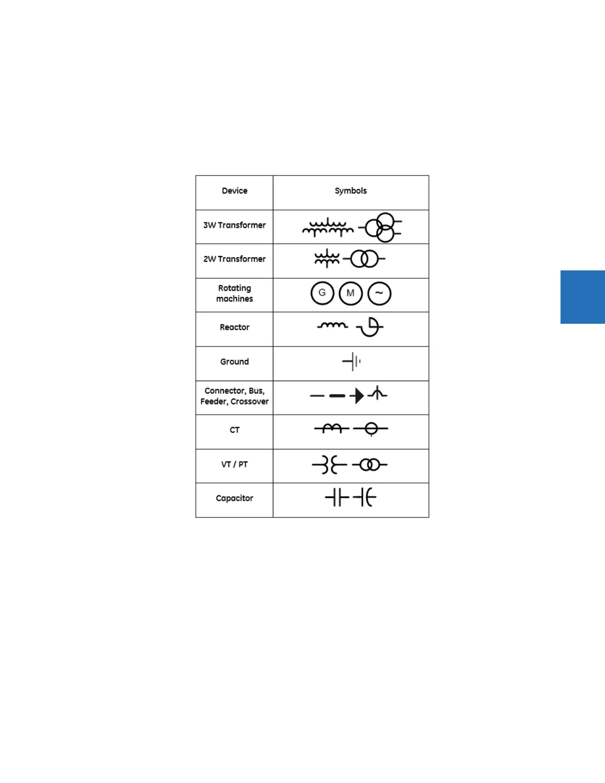
Static symbols
Static symbols depicting power system elements are available. For information, see the ANSI/IEEE 315A and IEC 60617
standards.
Up to 32 static symbols can be used per single-line diagram.
To add a symbol, click it in the toolbox, then click in the window. Double-click the symbol to open its properties window to
set orientation.
Figure 4-31: IEEE and IEC static symbols
Breaker and disconnect components
Breaker components and disconnect components are interfaces to the UR breaker control elements and disconnect
switch elements. On a UR device they show dynamically the breaker or disconnect status as calculated by the element,
and provide means to open, close, tag, bypass interlock, and substitute (force status of) the element. Breaker components
in addition provide means to enable/disable breaker autoreclose.
Each breaker and disconnect component can be configured to use UR-style symbols, IEC symbols, or simple square/slash
symbols as shown in the following figure. The symbols assume horizontal symbol orientation, red - closed color, and green
- open scheme. With vertical orientation, they are rotated 90 degrees.