4-26 C70 CAPACITOR BANK PROTECTION AND CONTROL SYSTEM – INSTRUCTION MANUAL
FRONT PANEL INTERFACE CHAPTER 4: INTERFACES
4
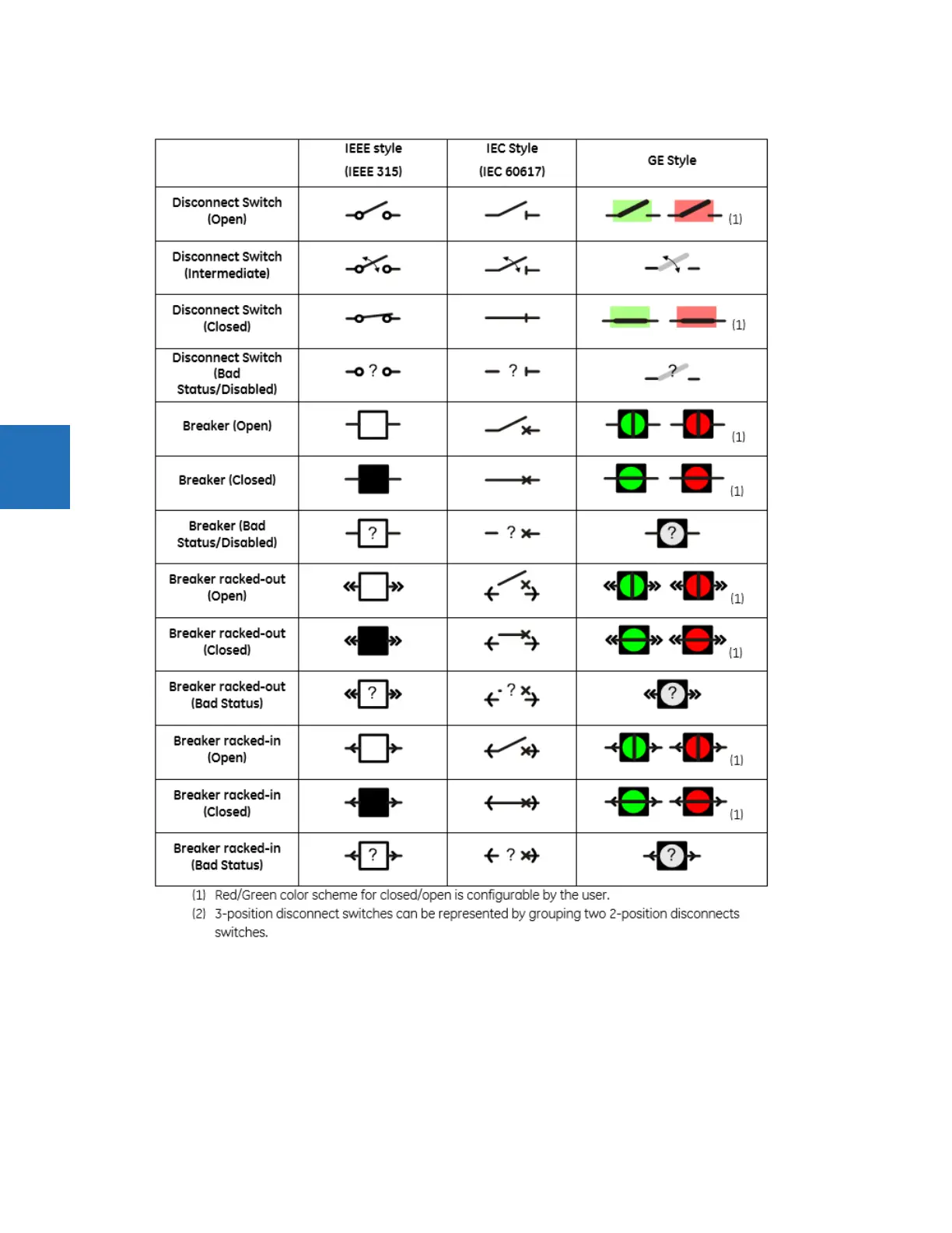
Figure 4-32: Single-line diagram symbols
To add a breaker or disconnect component, click it in the toolbox, then click in the window. Up to 10 dynamic components
can be added to each single-line diagram.
Breaker and disconnect components have three different parts: label, symbol, and flags. Drag each of its parts to their final
locations. Double or right-click any of these parts to open the properties window. Properties that can be edited are label
text, breaker control element or disconnect switch element number, symbol orientation (horizontal or vertical), color
scheme (red - closed, or red - open), and assigned side button (if any). If the selected breaker or disconnect element does