CHAPTER 4: INTERFACES FRONT PANEL INTERFACE
C70 CAPACITOR BANK PROTECTION AND CONTROL SYSTEM – INSTRUCTION MANUAL 4-27
4
not exist in the target relay or has not been enabled, then the component is displayed in the graphical front panel and in
the drawing edit window in grey. The color scheme selection has no effect when an IEC style symbol is used because IEC
style symbols do not use color.
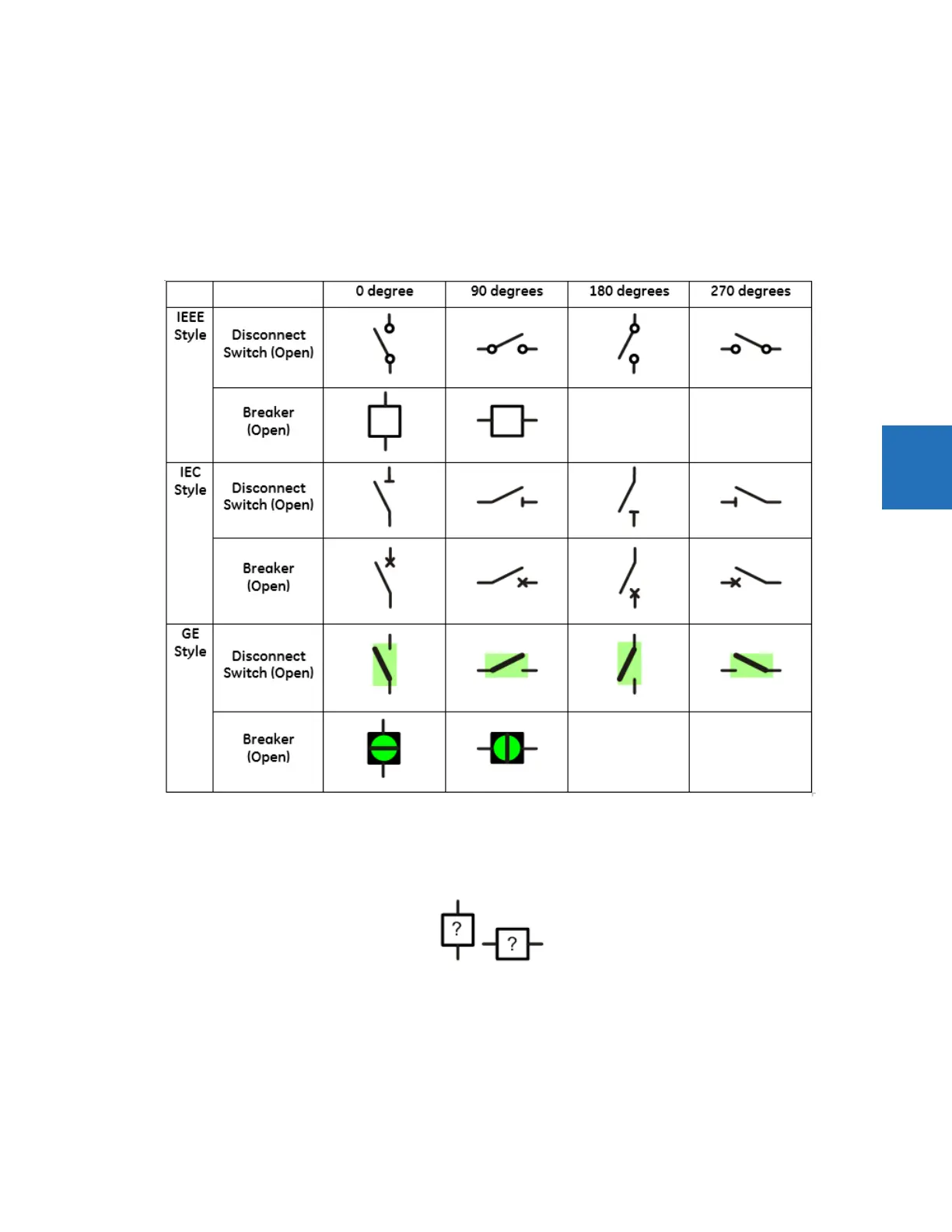
Symbol orientation
The figure shows the orientation available for the breaker and disconnect switch (taking Open status as examples). The
default position is 0 degrees.
Figure 4-33: Single-line diagram symbol orientation
A question mark displays in a symbol on the graphical front panel when status is bad. The question mark does not rotate
with orientation.
Figure 4-34: Symbols when status is bad
The following figures show the orientation available for the static components. The default position is 0 degrees.