5-134 C70 CAPACITOR BANK PROTECTION AND CONTROL SYSTEM – INSTRUCTION MANUAL
PRODUCT SETUP CHAPTER 5: SETTINGS
5
DIRECT OUTPUT DEVICE ID: “3”
DIRECT I/O CH1 RING CONFIGURATION: “Yes”
DIRECT I/O CH2 RING CONFIGURATION: “Yes”
For UR-series IED 4:
DIRECT OUTPUT DEVICE ID: “4”
DIRECT I/O CH1 RING CONFIGURATION: “Yes”
DIRECT I/O CH2 RING CONFIGURATION: “Yes”
Message delivery time is approximately 0.2 of power system cycle (at 128 kbps) times number of ‘bridges’ between the
origin and destination. Dual-ring configuration effectively reduces the maximum ‘communications distance’ by a factor of
two.
In this configuration the following delivery times are expected (at 128 kbps) if both rings are healthy:
IED 1 to IED 2: 0.2 of power system cycle
IED 1 to IED 3: 0.4 of power system cycle
IED 1 to IED 4: 0.2 of power system cycle
IED 2 to IED 3: 0.2 of power system cycle
IED 2 to IED 4: 0.4 of power system cycle
IED 3 to IED 4: 0.2 of power system cycle
If one ring is broken (say TX2-RX2) the delivery times are as follows:
IED 1 to IED 2: 0.2 of power system cycle
IED 1 to IED 3: 0.4 of power system cycle
IED 1 to IED 4: 0.6 of power system cycle
IED 2 to IED 3: 0.2 of power system cycle
IED 2 to IED 4: 0.4 of power system cycle
IED 3 to IED 4: 0.2 of power system cycle
A coordinating timer for this bus protection scheme could be selected to cover the worst case scenario (0.4 of a power
system cycle). Upon detecting a broken ring, the coordination time is adaptively increased to 0.6 of a power system cycle.
The complete application requires addressing a number of issues, such as failure of both the communications rings, failure
or out-of-service conditions of one of the relays, and so on. Self-monitoring flags of the direct inputs and outputs feature
primarily are used to address these concerns.
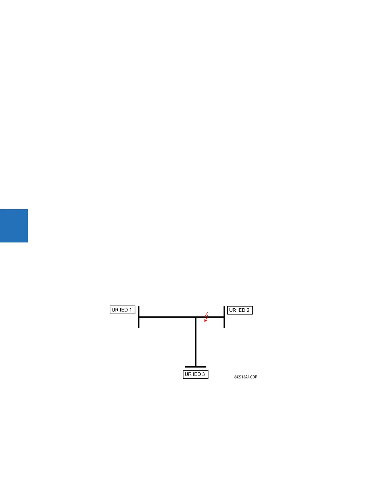
Example 3: Pilot-aided schemes
Consider the three-terminal line protection application shown.
Figure 5-62: Three-terminal line application
A permissive pilot-aided scheme can be implemented in a two-ring configuration, shown as follows (IEDs 1 and 2
constitute a first ring, while IEDs 2 and 3 constitute a second ring).