CHAPTER 5: SETTINGS PRODUCT SETUP
C70 CAPACITOR BANK PROTECTION AND CONTROL SYSTEM – INSTRUCTION MANUAL 5-135
5
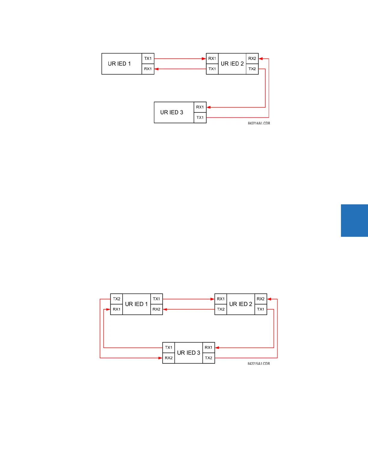
Figure 5-63: Single-channel open loop configuration
In this application, apply the following settings. For UR-series IED 1:
DIRECT OUTPUT DEVICE ID: “1”
DIRECT I/O CH1 RING CONFIGURATION: “Yes”
DIRECT I/O CH2 RING CONFIGURATION: “Yes”
For UR-series IED 2:
DIRECT OUTPUT DEVICE ID: “2”
DIRECT I/O CH1 RING CONFIGURATION: “Yes”
DIRECT I/O CH2 RING CONFIGURATION: “Yes”
For UR-series IED 3:
DIRECT OUTPUT DEVICE ID: “3”
DIRECT I/O CH1 RING CONFIGURATION: “Yes”
DIRECT I/O CH2 RING CONFIGURATION: “Yes”
In this configuration the following delivery times are expected (at 128 kbps):
IED 1 to IED 2: 0.2 of power system cycle
IED 1 to IED 3: 0.5 of power system cycle
IED 2 to IED 3: 0.2 of power system cycle
In this scheme, IEDs 1 and 3 do not communicate directly. IED 2 must be configured to forward the messages as explained
in the Inputs and Outputs section. Implement a blocking pilot-aided scheme with more security and, ideally, faster
message delivery time. This is accomplished using a dual-ring configuration as shown here.
Figure 5-64: Dual-channel closed loop (dual-ring) configuration
In this application, apply the following settings. For UR-series IED 1:
DIRECT OUTPUT DEVICE ID: “1”
DIRECT I/O CH1 RING CONFIGURATION: “Yes”
DIRECT I/O CH2 RING CONFIGURATION: “Yes”
For UR-series IED 2: