CHAPTER 5: SETTINGS FLEXLOGIC
C70 CAPACITOR BANK PROTECTION AND CONTROL SYSTEM – INSTRUCTION MANUAL 5-173
5
ELEMENT:
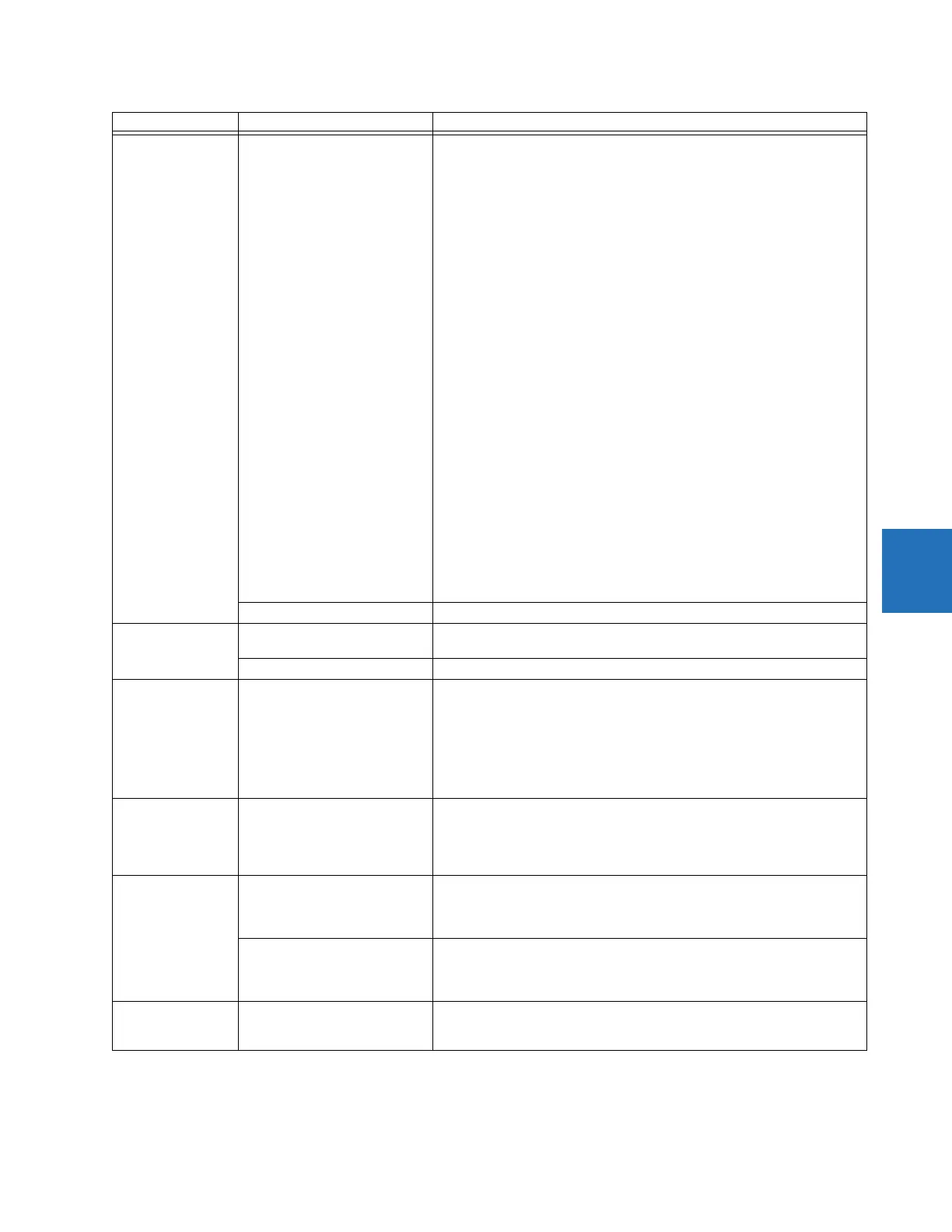
Voltage differential
VOLT DIF 1 STG1A PKP
VOLT DIF 1 STG1B PKP
VOLT DIF 1 STG1C PKP
VOLT DIF 1 STG2A PKP
VOLT DIF 1 STG2B PKP
VOLT DIF 1 STG2C PKP
VOLT DIF 1 STG3A PKP
VOLT DIF 1 STG3B PKP
VOLT DIF 1 STG3C PKP
VOLT DIF 1 STG4A PKP
VOLT DIF 1 STG4B PKP
VOLT DIF 1 STG4C PKP
VOLT DIF 1 PKP A
VOLT DIF 1 PKP B
VOLT DIF 1 PKP C
VOLT DIF 1 PKP
VOLT DIF 1 DPO
VOLT DIF 1 STG1A OP
VOLT DIF 1 STG1B OP
VOLT DIF 1 STG1C OP
VOLT DIF 1 STG2A OP
VOLT DIF 1 STG2B OP
VOLT DIF 1 STG2C OP
VOLT DIF 1 STG3A OP
VOLT DIF 1 STG3B OP
VOLT DIF 1 STG3C OP
VOLT DIF 1 STG4A OP
VOLT DIF 1 STG4B OP
VOLT DIF 1 STG4C OP
VOLT DIF 1 OP A
VOLT DIF 1 OP B
VOLT DIF 1 OP C
VOLT DIF 1 OP
Voltage differential element 1 picked up in phase A of stage 1
Voltage differential element 1 picked up in phase B of stage 1
Voltage differential element 1 picked up in phase C of stage 1
Voltage differential element 1 picked up in phase A of stage 2
Voltage differential element 1 picked up in phase B of stage 2
Voltage differential element 1 picked up in phase C of stage 2
Voltage differential element 1 picked up in phase A of stage 3
Voltage differential element 1 picked up in phase B of stage 3
Voltage differential element 1 picked up in phase C of stage 3
Voltage differential element 1 picked up in phase A of stage 4
Voltage differential element 1 picked up in phase B of stage 4
Voltage differential element 1 picked up in phase C of stage 4
Voltage differential element 1 picked up in phase A
Voltage differential element 1 picked up in phase B
Voltage differential element 1 picked up in phase C
Voltage differential element 1 picked up
Voltage differential element 1 dropped out
Voltage differential element 1 operated in phase A of stage 1
Voltage differential element 1 operated in phase B of stage 1
Voltage differential element 1 operated in phase C of stage 1
Voltage differential element 1 operated in phase A of stage 2
Voltage differential element 1 operated in phase B of stage 2
Voltage differential element 1 operated in phase C of stage 2
Voltage differential element 1 operated in phase A of stage 3
Voltage differential element 1 operated in phase B of stage 3
Voltage differential element 1 operated in phase C of stage 3
Voltage differential element 1 operated in phase A of stage 4
Voltage differential element 1 operated in phase B of stage 4
Voltage differential element 1 operated in phase C of stage 4
Voltage differential element 1 operated in phase A
Voltage differential element 1 operated in phase B
Voltage differential element 1 operated in phase C
Voltage differential element 1 operated
VOLT DIF 2 to 3 Same set of operands as shown for VOLT DIF 1
FIXED OPERANDS Off Logic = 0. Does nothing and can be used as a delimiter in an equation list;
used as ‘Disable’ by other features.
On Logic = 1. Can be used as a test setting.
INPUTS/OUTPUTS:
Contact inputs
Cont Ip 1 On
Cont Ip 2 On
↓
Cont Ip 1 Off
Cont Ip 2 Off
↓
Cont Ip 120 On
Cont Ip 120 Off
(does not appear unless ordered)
(does not appear unless ordered)
↓
(does not appear unless ordered)
(does not appear unless ordered)
↓
(does not appear unless ordered)
(does not appear unless ordered)
INPUTS/OUTPUTS:
Contact outputs,
current
(from detector on
form-A output only)
Cont Op 1 IOn
Cont Op 2 IOn
↓
Cont Op 72 IOn
(does not appear unless ordered)
(does not appear unless ordered)
↓
(does not appear unless ordered)
INPUTS/OUTPUTS:
Contact outputs,
voltage
(from detector on
form-A output only)
Cont Op 1 VOn
Cont Op 2 VOn
↓
Cont Op 72 VOn
(does not appear unless ordered)
(does not appear unless ordered)
↓
(does not appear unless ordered)
Cont Op 1 VOff
Cont Op 2 VOff
↓
Cont Op 72 VOff
(does not appear unless ordered)
(does not appear unless ordered)
↓
(does not appear unless ordered)
INPUTS/OUTPUTS:
Direct inputs
DIRECT INPUT 1 On
↓
DIRECT INPUT 32 On
Flag is set, logic=1
↓
Flag is set, logic=1
Operand type Operand syntax Operand description

 Loading...