5-242 C70 CAPACITOR BANK PROTECTION AND CONTROL SYSTEM – INSTRUCTION MANUAL
GROUPED ELEMENTS CHAPTER 5: SETTINGS
5
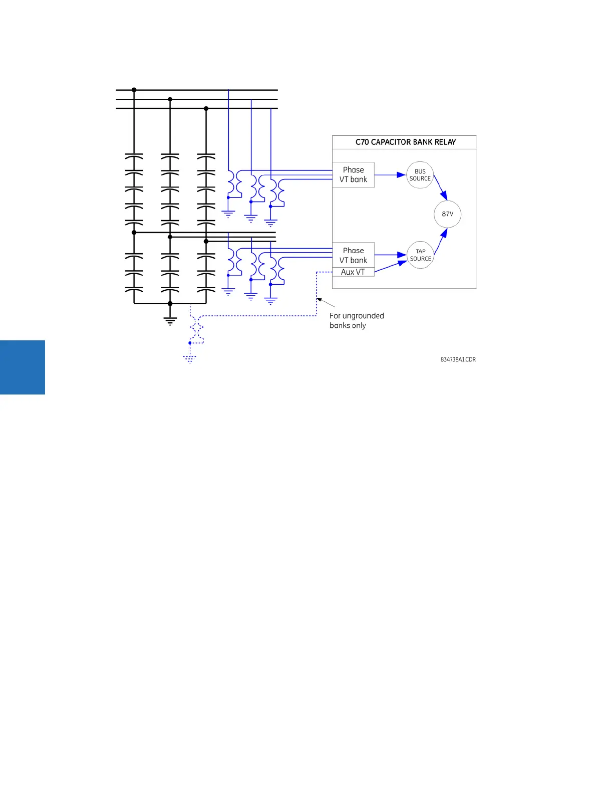
Figure 5-128: Voltage differential basic connections
The function works with grounded and ungrounded banks. In the latter case, the neutral point voltage must be measured
by the relay. For information, see the Application of Settings chapter.
The following settings are available for each voltage differential element.
VOLTAGE DIF 1 BUS SOURCE — Indicates signal source that signifies the bus voltage of the bank. The function uses this
source as reference for pu settings of pickup thresholds, and scales the tap voltages to this signal level. The VT ratio and
secondary nominal voltage are set under separate menu. Voltages of this source must be connected in wye for the
function to operate.
VOLTAGE DIF 1 TAP SOURCE — Indicates signal source that signifies the tap voltage of the bank. The function scales this
voltage to the bus level using the matching factor setting. The matching is performed on primary voltages, or per unit of
the bus voltage. The VT ratio and secondary nominal voltage are set under separate menu. Voltages of this source must be
connected in wye for the function to operate. If this function is used on ungrounded banks, the tap source must have the
neutral point voltage of the bank configured under the auxiliary voltage channel. That auxiliary voltage must be labelled
“Vn” under the VT setup menu.
VOLTAGE DIF 1 BANK GROUND — Indicates if the protected bank is grounded or ungrounded. In the latter case, the auxiliary
voltage configured under the tap source is subtracted from the phase voltages of both the bus and tap. This results in the
actual voltage drop along the capacitor string, and thus facilitates the voltage differential principle. The relay
automatically compensates for different VT ratios and secondary voltages of the neutral point voltage and the bus and tap
voltages.
VOLTAGE DIF 1 MATCH FACTOR A to VOLTAGE DIF 1 MATCH FACTOR C — Specifies the division ratio of the healthy bank, that is,
the ratio between the bus and tap voltages (value greater than 1). The matching factor is applied as a multiplier for the
primary tap voltage before comparing with the primary bus voltage. Quality of balancing the bank with a given value of
this setting can be viewed under the
ACTUAL VALUES menu. An automatic setting procedure is available under the
COMMANDS menu to calculate the matching factors automatically.
VOLTAGE DIF 1 STG 1A PICKUP to VOLTAGE DIF 1 STG 4C PICKUP — Specify pickup thresholds for stages 1 through 4 for phases
A to C in per-units (pu) of the nominal bus voltage. A value of 1 pu is a product of the nominal secondary voltage and VT
ratio of the voltage bank configured under the bus source of this function. Four independent stages are provided for each
phase of protection.