CHAPTER 5: SETTINGS CONTROL ELEMENTS
C70 CAPACITOR BANK PROTECTION AND CONTROL SYSTEM – INSTRUCTION MANUAL 5-269
5
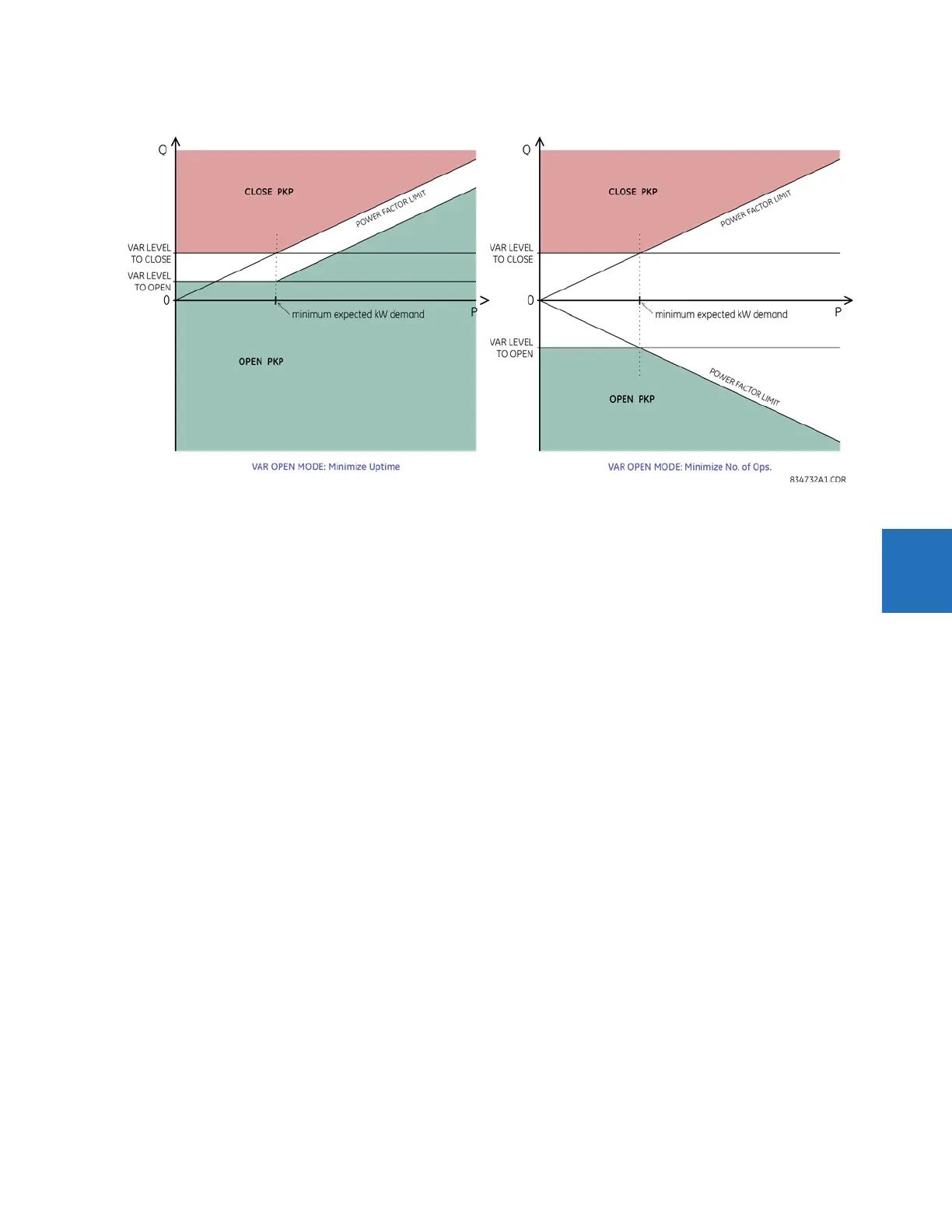
Figure 5-145: Automatic voltage regulator pickup characteristics in "VAR" mode
Take care that the settings do not result in the capacitor being continuously cycled close and open. In the voltage mode,
set the close voltage settings lower than the open voltage setting by more than the voltage change expected from
capacitor switching, plus margin. Similarly in the “VAR” mode, set the close var setting higher than the open var setting by
more than the expected var change due to capacitor switching, plus margin. For configurations where the capacitor
current is not included in the measured current, there can still be a measured var change due to loads whose power factor
increases with increasing voltage. In general, the larger the margin, the less the capacitor is switched.
Set delays long enough to avoid undesired operations on transient conditions. Depending on the application, this can
include operations for noise hits, for transient voltage depressions accompanying successful fault clearance, and short-
term voltage conditions pending automatic reclosure. Delays can also be used to time co-ordinate the switching of
multiple capacitor banks, or sections of the same bank.
The following settings are available.
AVR 1 SOURCE — This setting selects signal source of the control variables of interest. In case of voltage control applications,
the selected source needs to have the appropriate voltages configured for proper operation. For example, when using
positive-sequence voltage as a control variable, phase voltages must be configured under the source; or when using
single-phase auxiliary voltage, the auxiliary source voltage must be configured. In case of “VAR” mode and of voltage
mode with voltage drop compensation, the indicated source must be configured with phase voltages and currents into the
regulated load or bus, and should include the capacitor current. If the source indicated here does not support the control
variable selected, the function will restrain itself from operating, and assert neither the close or open command.
AVR 1 MINIMUM VOLTAGE — This value sets the minimum voltage for capacitor switching, to discriminate against loss of
voltage. For voltage mode, this setting applies to the voltage selected for control. For “VAR” mode, this setting applies to
the positive sequence voltage.
AVR 1 CONTROL MODE — This setting selects either voltage control for voltage regulation applications, or var control for
power factor/reactive power regulation applications.
AVR 1 VOLT OPERATING SIGNAL — When the control mode is voltage, this setting is used to select whether the AVR responds
to an individual phase-to-phase voltage or phase-to-ground voltage, the average of the three phase-to-phase voltages,
the positive sequence voltage, or the auxiliary RMS voltage. The ability to select the same voltage quantity as is used by
other AVRs facilitates coordination with those AVRs.
AVR 1 VOLT LEVEL TO CLOSE — In the voltage mode, this setting specifies the voltage level at or below which to issue the
close command.
AVR 1 VOLT LEVEL TO OPEN — In the voltage mode, this setting specifies the voltage level at or above which to issue the open
command. The following figure illustrates voltage control level settings.