5-270 C70 CAPACITOR BANK PROTECTION AND CONTROL SYSTEM – INSTRUCTION MANUAL
CONTROL ELEMENTS CHAPTER 5: SETTINGS
5
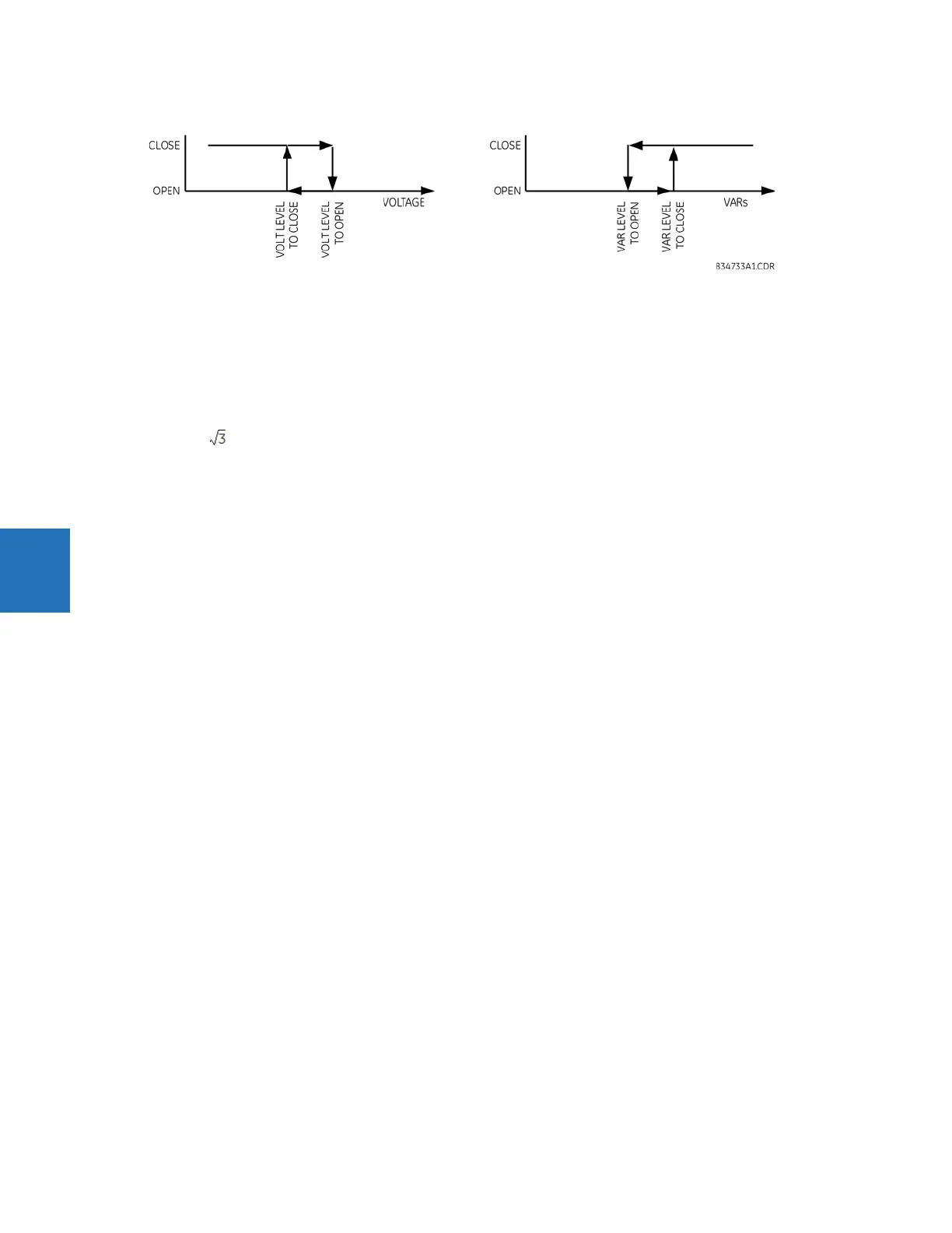
Figure 5-146: Close and open levels when controlling voltage or VARs
AVR 1 VOLT DROP COMPENS Z — In the voltage mode, this setting allows compensating for voltage drop on the line when the
relay measuring point is located upstream of the load. Positive-sequence line impedance is entered in secondary ohms.
Compensation cannot exceed 20% of the nominal phase voltage.
AVR 1 VOLT DROP COMPENS RCA — In the voltage mode, this setting specifies the angle of the line impedance for voltage
drop calculations.
AVR 1 VAR LEVEL TO CLOSE — In the “VAR” mode, this setting specifies level for the three-phase reactive power level at or
above which to issue the close command. The 1 pu value is the product of the nominal primary phase-to-phase voltage,
the CT primary, and . When the source current is an internal summation of two or more CT bank currents, the largest CT
primary is used to define the 1 pu value for this setting.
AVR 1 VAR LEVEL TO OPEN — In the “VAR” mode, this setting specifies level for the three-phase reactive power level at or
below which to issue the OPEN command. The 1 pu value is defined as for the
VAR LEVEL TO CLOSE setting.
AVR 1 POWER FACTOR LIMIT — In the “VAR” mode, this setting specifies the power factor below which close commands are
allowed. Also affects open commands as shown in the above figure. If set to “1.00”, the power factor has no effect.
AVR 1 VAR OPEN MODE — Selects the close command characteristic, either “Minimize No. of Ops.” (minimize number of
operations) or “Minimize Uptime”, as described earlier in the Automatic Voltage Regulator Pickup Characteristics in “VAR”
Mode diagram.
AVR 1 DELAY BEFORE CLOSE — Specifies delay before issuing the close command, and is used to coordinate with other
regulators, or to ride through abnormal system conditions such as faults or re-close sequences.
AVR 1 DELAY BEFORE OPEN — Specifies delay before issuing the open command, and is used to coordinate with other
regulators, or to ride through abnormal system conditions such as faults or re-close sequences.
AVR 1 BLOCK — Specifies a dynamic blocking condition. When blocked the element resets its output flags and internal
timers. VT fuse fail is a typical application.