8-8 C70 CAPACITOR BANK PROTECTION AND CONTROL SYSTEM – INSTRUCTION MANUAL
PROTECTION METHODS FOR CAPACITOR BANKS CHAPTER 8: APPLICATION OF SETTINGS
8
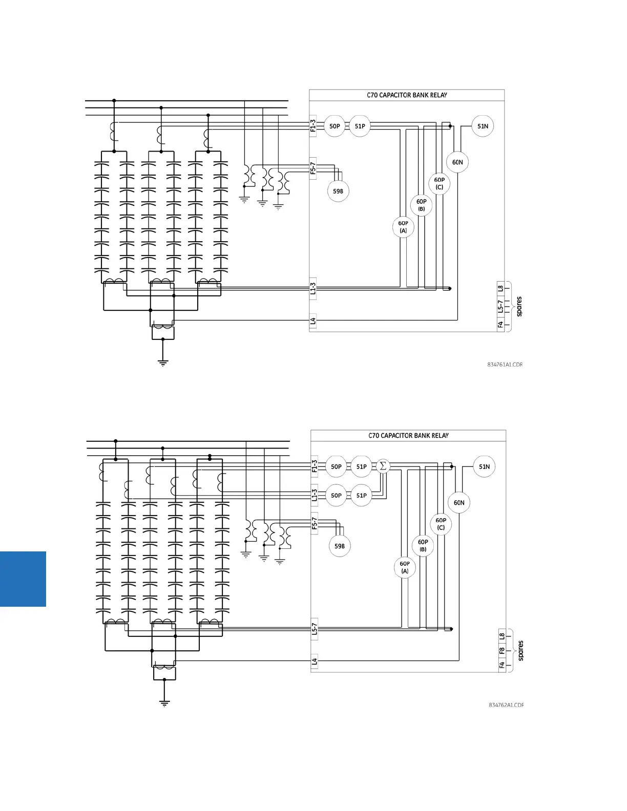
Figure 8-9: Parallel banks, grounded, no tap available, current balance protection
The following figure illustrates parallel capacitor banks, grounded, no tap available, with current unbalance protection and
high-side CTs for each bank. In this case, two CT/VT modules are required.
Figure 8-10: Parallel banks, grounded, no tap, with current balance protection and high-side CTs