9-12 C70 CAPACITOR BANK PROTECTION AND CONTROL SYSTEM – INSTRUCTION MANUAL
OVERVIEW CHAPTER 9: THEORY OF OPERATION
9
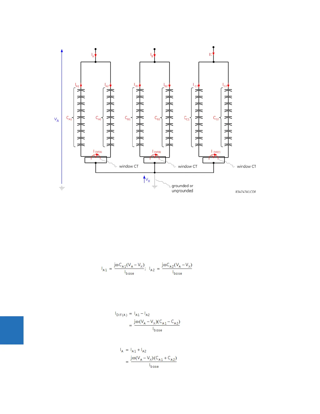
Figure 9-5: Phase current unbalance application
The protection operates when the operate signal is greater than the set pickup level for the set pickup delay. Identical
relations apply to phases B and C.
Sensitivity is the key performance parameter. The applied comparator uses a simple integration method in addition to the
standard hysteresis approach, to deal with chattering of the operating signal at the boundary of operation.
9.1.5.2 Balanced case
To understand phase current unbalance protection, first note that the currents are driven by the individual admittances in
each string:
Eq. 9-44
In these equations, I
base
represents the differential CT primary current rating. This places the string currents on the same
per-unit base used by the C70. Voltages are expressed in primary volts, capacitances in Farads, and frequency in radians
per second.
The differential current is the vector difference between the two currents:
Eq. 9-45
The total phase current is the vector sum of the two currents:
Eq. 9-46