CHAPTER 9: THEORY OF OPERATION OVERVIEW
C70 CAPACITOR BANK PROTECTION AND CONTROL SYSTEM – INSTRUCTION MANUAL 9-13
9
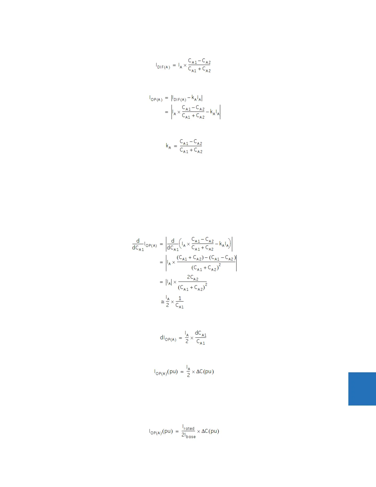
Inserting equation 9.46 into equation 9.45, to eliminate the voltages, we get:
Eq. 9-47
Inserting this value into equation 9.43, we have:
Eq. 9-48
The capacitor bank leg-A inherent unbalance factor setting k
A
is chosen to be:
Eq. 9-49
As can be seen from the previous two equations, the initial operating signal is zero.
9.1.5.3 Sensitivity
Now consider the consequences of an element failure in a typical string, say string A1, making a small capacitance change
in C
A1
capacitance. The effect on the operating signal can be calculated by taking the derivative of equation 9.48 with
respect to C
A1
.
In the general case, the derivative of the absolute value function is messy, but in our case where the initial value is zero, the
derivative of the absolute function is simply the absolute value of the derivative of its argument. We assume here that I
A
is
constant, which investigation has shown results in negligible error. The derivative is thus:
Eq. 9-50
The last step assumes C
A1
≅ C
A2
and replaces the phase current vector with its magnitude. This can be written as:
Eq. 9-51
Alternatively, we can say:
Eq. 9-52
where ΔC(pu) represents the capacitance change as a per-unit of the string capacitance, and I
OP(A)
(pu) represents the
operating signal resulting from the failure in per-unit of the nominal current of the differential source. I
A
is phase A terminal
current on the same base. When the system is normal (no fault), I
A
can be taken as the capacitor bank rated primary per-
phase current I
rated
converted to the differential source base. For example, I
A
=I
rated
/I
base
, where I
base
is again the
differential CT primary current rating, or:
Eq. 9-53