CHAPTER 9: THEORY OF OPERATION OVERVIEW
C70 CAPACITOR BANK PROTECTION AND CONTROL SYSTEM – INSTRUCTION MANUAL 9-15
9
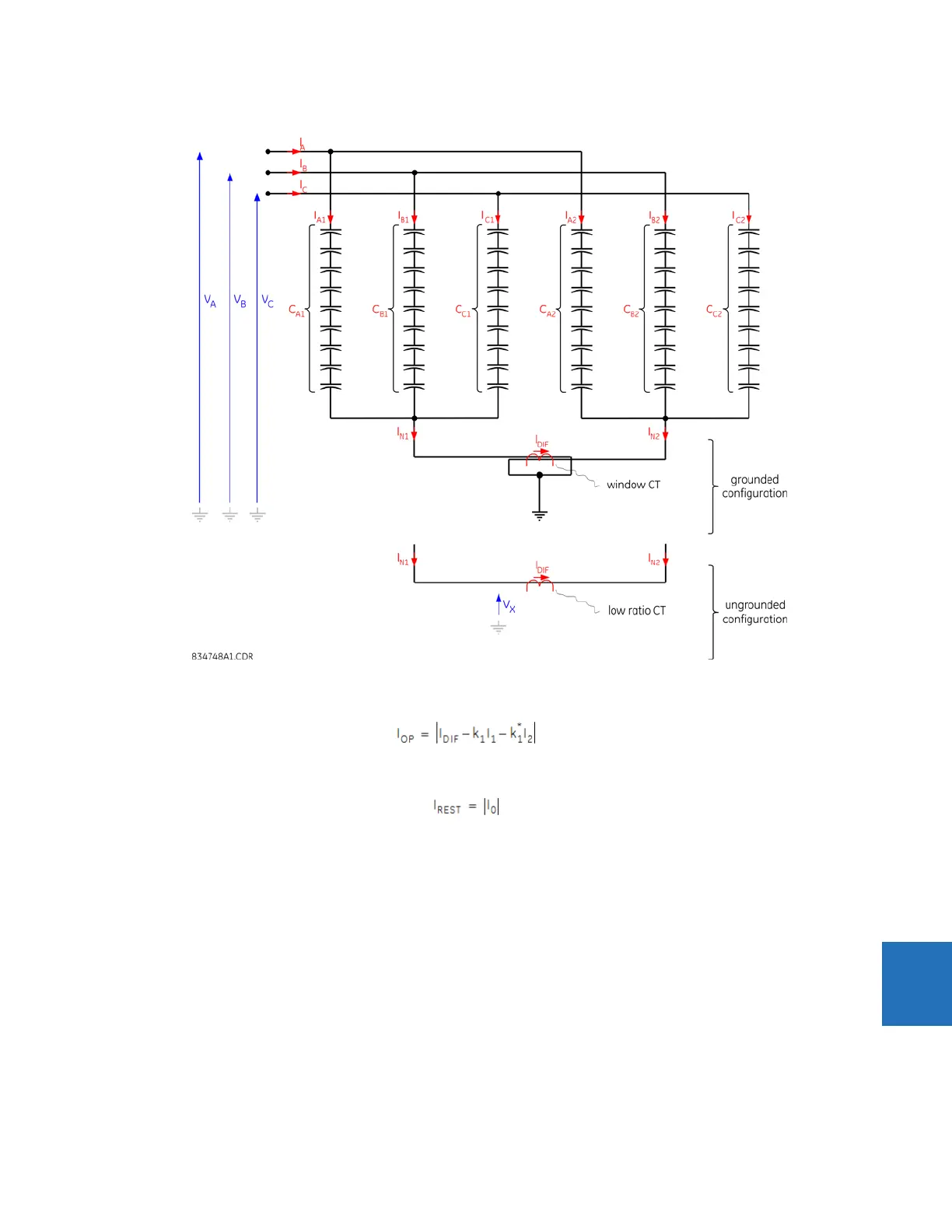
Figure 9-6: Neutral current unbalance application
The neutral current unbalance protection uses the following operate signal:
Eq. 9-54
The neutral current unbalance protection uses the following restraint signal:
Eq. 9-55
where k
1
represents the vector capacitor bank positive sequence inherent unbalance factor setting, and k
1
* represents the
complex conjugate of k
1
. The currents are as defined in the figure and are in per-unit values of the nominal current of the
bank source ground current channel.
These equations involve phasors, not magnitudes; that is, the vector sum of the currents is created by the protection
function implementing the method. The protection operates when the operate signal is greater than the set pickup level
for the set pickup delay.
Sensitivity is the key performance parameter. The applied comparator uses a simple integration method in addition to the
standard hysteresis approach, to deal with chattering of the operating signal at the boundary of operation.